
Ultrasonic cleaning device for film coated graphite frame

An ultrasonic and cleaning tank technology is applied in the field of cleaning devices for graphite frames for silicon wafer coating, which can solve the problems of long soaking time, large number of turnover graphite frames, and low cleaning efficiency.

Active Publication Date: 2014-07-23
EGING PHOTOVOLTAIC TECHNOLOGY CO LTD
View PDF7 Cites 0 Cited by
  • Summary
  • Abstract
  • Description
  • Claims
  • Application Information

AI Technical Summary

Problems solved by technology

The cleaning effect of this soaking and cleaning method is not good, and it is difficult to clean off the silicon nitride or other sundries attached to the corners of the graphite frame. The number of graphite frames is large, not only the one-time investment cost is high, but also the floor area is large

Method used


Image

  • Ultrasonic cleaning device for film coated graphite frame
  • Ultrasonic cleaning device for film coated graphite frame

Examples


specific Embodiment approach

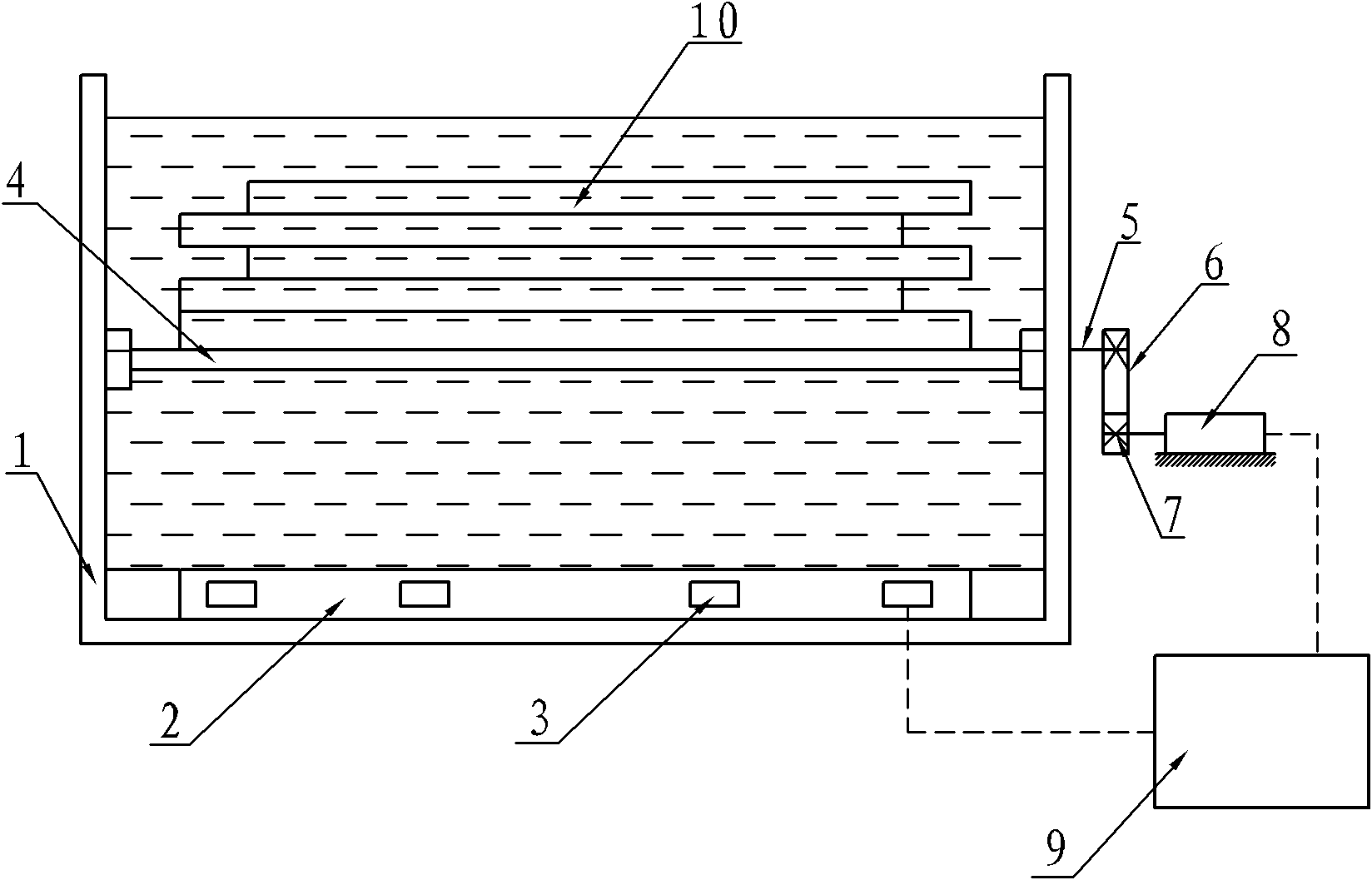
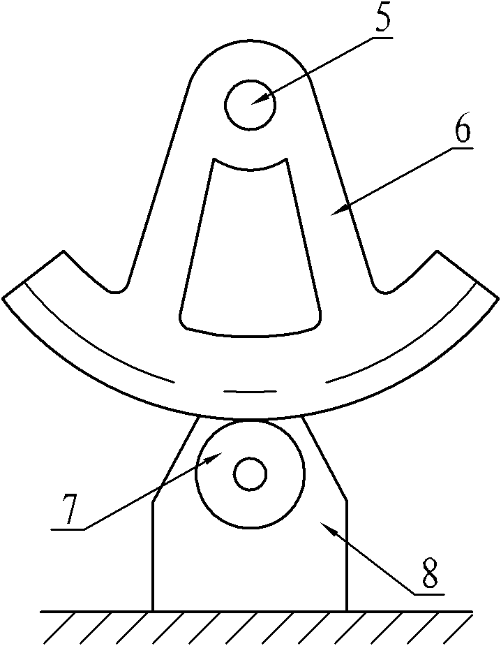
[0012] Such as Figure 1~2 As shown, an ultrasonic cleaning device for a coated graphite frame includes a cleaning tank 1, an ultrasonic vibrator mounting frame 2, an ultrasonic generator 3, a swing bearing frame 4, a supporting shaft 5, an bevel gear 6, a driving gear 7, and a servo motor 8 and the electronic control part 9, the ultrasonic generator 3 is arranged in the ultrasonic vibrator installation frame 2, the ultrasonic vibrator installation frame 2 is arranged at the bottom of the cleaning tank 1, the swing bearing frame 4 is installed in the cleaning tank 1 through the support shaft 5, and the support shaft 5 One end protrudes out of the cleaning tank 1, and a bevel gear 6 is installed on the protruding end of the support shaft 5. The driving gear 7 is installed on the output shaft of the servo motor 8, and the driving gear 7 is meshed with the bevel gear 6. The ultrasonic generator 3 and the servo motor 8 are electrically connected with the electric control part 9, t...


PUM


Abstract

The invention discloses an ultrasonic cleaning device for a film coated graphite frame, which comprises a cleaning tank, an ultrasonic vibrator mounting frame, an ultrasonic generator, a swing bearing frame, a supporting axle, a bevel gear, a driving gear, a servomotor and an electric control part, wherein the ultrasonic generator is arranged in the ultrasonic vibrator mounting frame, and is arranged at the bottom of the cleaning tank; the swing bearing frame is arranged in the cleaning tank in a swing mode; and the servomotor drives the swing bearing frame to reciprocate in a mode of meshed transmission of the driving gear and the bevel gear. The ultrasonic generator accelerates the reaction of a hydrofluoric acid solution and silicon nitride, and the left-right swing of the swing bearing frame increases the contact of the graphite frame and the hydrofluoric acid solution, can homogenize the concentration of the hydrofluoric acid solution in the cleaning tank and is more favorable for the reaction of the hydrofluoric acid solution and the silicon nitride. Compared with the prior art, the ultrasonic cleaning device is high in speed and good in cleaning effect and can remove silicon nitride or dirt attached to the corners of the graphite frame, and the circulating graphite frames required by production are only 1 / 2 of the graphite frames in the prior art.

Description

technical field [0001] The invention relates to a cleaning device for a solar cell silicon chip, in particular to a cleaning device for a graphite frame used for coating a silicon chip. Background technique [0002] Making anti-reflection coatings on the surface of silicon wafers can reduce optical loss and recombination loss, and increase the output power of solar cells. At present, large-scale production of solar cells uses flat-plate plasma chemical deposition, that is, PECVD to make anti-reflection coatings. The main process of the chemical deposition method is as follows: first, a copper tube is placed in a closed quartz tube, the quartz tube is placed in the deposition source, the deposition source is evacuated, and then silane and ammonia are introduced, and the copper tube emits microwaves. , under certain temperature conditions, silane and ammonia react to form silicon nitride, which is the material of the anti-reflection film. Since the cell is placed on the graphi...

Claims


Application Information

Patent Timeline
Patent Type & Authority Patents(China)
IPC IPC(8): B08B3/12H01L31/18
CPCY02P70/50
Inventor 姚伟忠
Owner EGING PHOTOVOLTAIC TECHNOLOGY CO LTD
Learn More