
Cutting device for communication wire and cable shielding layer

A cutting device, wire and cable technology, applied in the direction of cable installation, cable installation device, disassembly/armored cable equipment, etc., can solve the problems of slow manual stripping speed, poor stripping effect, cable core damage, etc., to avoid cutting The effect of unevenness, neat incision and fast cutting speed

Active Publication Date: 2020-01-07
四川越洋电子科技有限责任公司
View PDF11 Cites 5 Cited by
  • Summary
  • Abstract
  • Description
  • Claims
  • Application Information

AI Technical Summary

Problems solved by technology

[0004] The purpose of the present invention is to solve the disadvantages of slow manual stripping, low efficiency, poor stripping effect, and easy damage to the cable core due to improper operation in the prior art, and proposes a communication wire and cable shielding layer cutting device

Method used


Image

  • Cutting device for communication wire and cable shielding layer
  • Cutting device for communication wire and cable shielding layer
  • Cutting device for communication wire and cable shielding layer

Examples


Embodiment Construction

[0029] The following will clearly and completely describe the technical solutions in the embodiments of the present invention with reference to the accompanying drawings in the embodiments of the present invention. Obviously, the described embodiments are only some, not all, embodiments of the present invention.

[0030] In describing the present invention, it should be understood that the terms "upper", "lower", "front", "rear", "left", "right", "top", "bottom", "inner", " The orientation or positional relationship indicated by "outside", etc. is based on the orientation or positional relationship shown in the drawings, and is only for the convenience of describing the present invention and simplifying the description, rather than indicating or implying that the referred device or element must have a specific orientation, so as to Specific orientation configurations and operations, therefore, are not to be construed as limitations on the invention.

[0031] refer to Figure ...


PUM


Abstract

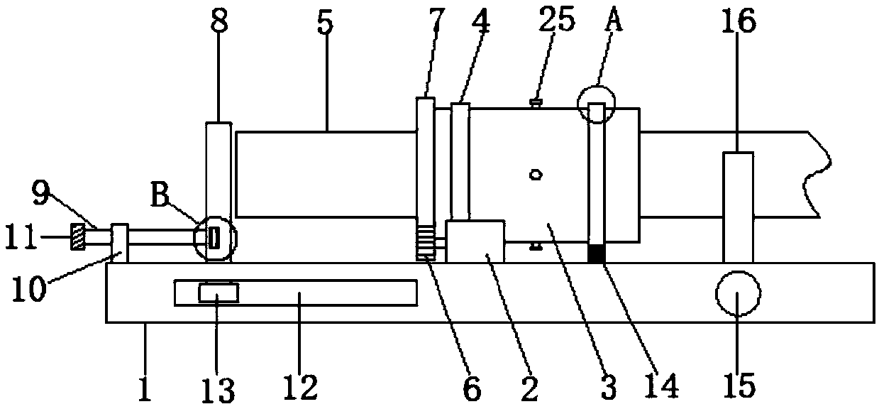
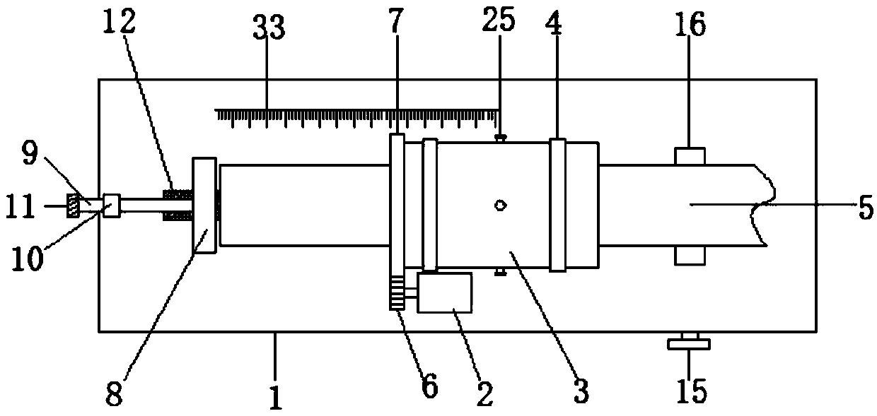
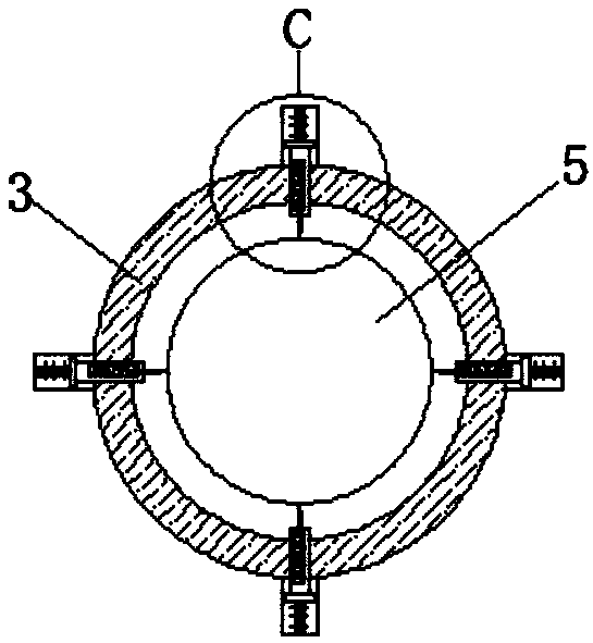
The invention discloses a cutting device for a communication wire and cable shielding layer. The device comprises a bottom plate, and a motor and a sleeve are mounted on the top wall of the bottom plate, wherein the motor is located at the outer side of the sleeve; two annular groove plates are arranged on the symmetrical outer side walls of the sleeve, and supporting plates are mounted on the bottom walls of the two annular groove plates; the bottom ends of the two supporting plates are mounted on the top wall of the bottom plate; a gear is installed at the driving end of the motor, a ring gear meshed with the gear is installed on the side wall of one end of the sleeve, a cable is arranged in the sleeve in a penetrating mode, four cutting devices are symmetrically installed on the outer side wall of the sleeve, and a positioning groove is formed in the top wall of the bottom plate. Through the mutual cooperation of all the structures, a shielding layer and an insulating layer of the cable can be cut, and the cutting length of the cable and the depth of a notch can be simply and effectively adjusted; the device has the beneficial effects that the cutting speed is high, the notch isneat, and a cable core cannot be damaged.

Description

technical field [0001] The invention relates to the technical field of cable processing, in particular to a cutting device for the shielding layer of communication wires and cables. Background technique [0002] Communication cable refers to the cable used for short-distance audio communication and long-distance high-frequency carrier and digital communication and signal transmission. It is one of the five major cable products in China. According to the purpose and scope of use of communication cables, it can be divided into six series of products, namely, local communication cables (including paper insulated local telephone cables, polyolefin insulated polyolefin sheathed local telephone cables), long-distance symmetrical cables (including paper insulated local telephone cables) Insulated high and low frequency long-distance symmetrical cables, copper core foam polyethylene high and low frequency long-distance symmetrical cables and digital transmission long-distance symmet...

Claims


Application Information

Patent Timeline
Patent Type & Authority Applications(China)
IPC IPC(8): H02G1/12
CPCH02G1/1265
Inventor 李祚文
Owner 四川越洋电子科技有限责任公司
Learn More