Vibration system of sound production device and the sound production device

A vibration system and sound-generating device technology, which is applied to sensors, electrical components, loudspeakers, etc., can solve the problems of insufficient low-frequency performance, small speaker excursion, poor low-frequency performance, etc., and achieve good neutrality, stability, and acoustic performance. Good, the effect of increasing the binding force

Inactive Publication Date: 2020-01-07
GOERTEK INC
View PDF5 Cites 0 Cited by
  • Summary
  • Abstract
  • Description
  • Claims
  • Application Information

AI Technical Summary

Problems solved by technology

This structure can be seen as figure 1 The enhanced version of the prior art structure can also make the structure very thin and narrow, and the power ratio it bears figure 1 The structure of the existing technology has been improved to a certain extent. The copper support piece used is glued to the paper cone and the ring, which is still a single suspension structure in terms of force analysis; in addition, it uses copper foil material as the support piece, and the metal material Physical characteristics determine that its stretchability is poor, and F0 is very high, which is not good in terms of the high compliance requirements of the speaker. It is conceivable that speakers with this structure often have a small stroke, which will result in insufficient low-frequency performance. At the same time, due to the copper The excessive limiting of the support piece to the speaker, its distortion value reaches 30-40% at 250-400Hz, which is far from meeting the standard of less than 10% for the product
Based on the above, from the perspective of acoustic performance, although this structural design can make the product relatively thin, the low-frequency performance is worse than the structure in prior art 1, and the overall sound quality is often poor
Furthermore, since it still belongs to the category of single suspension structure, there will also be similar figure 1 Various design flaws resulting from insufficient structural support

Method used


Image

  • Vibration system of sound production device and the sound production device
  • Vibration system of sound production device and the sound production device
  • Vibration system of sound production device and the sound production device

Examples


Embodiment

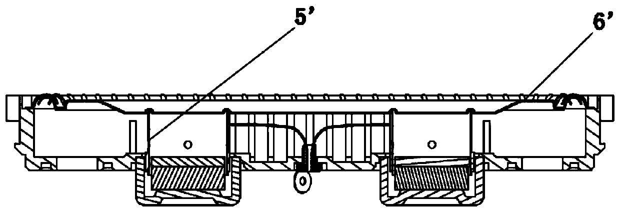
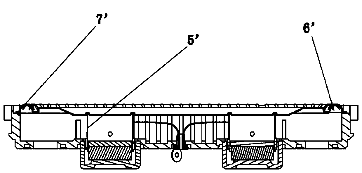
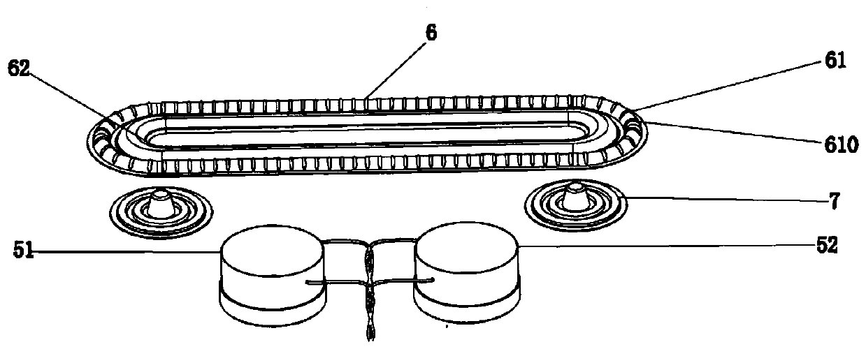
[0048] For example Figure 3 to Figure 5 As shown together, the vibration system of the sound generating device in this embodiment will be described by taking the vibration system of the dual-drive sound generating device applied to narrow and thin electronic equipment as an example. The vibration system includes a voice coil assembly 5 and a diaphragm assembly 6, wherein the voice coil assembly 5 includes two voice coil units, i.e. a first voice coil unit 51 and a second voice coil unit 52, and the diaphragm assembly 6 can be specifically configured as The strip shape includes an outer ring 61 and a body inside the outer ring 61 .

[0049] When assembled, the diaphragm assembly 6 is arranged horizontally as a whole, while the first voice coil unit 51 and the second voice coil unit 52 are arranged in parallel (parallel) in the horizontal direction, and the two voice coil units are arranged in the vertical direction Connect with the diaphragm assembly 6. Of course, specifical...


PUM


Abstract

The invention discloses a vibration system of a sound production device, and the system comprises a vibrating diaphragm assembly which including a folding ring located at the outer side and a body located at the inner side of the folding ring; a voice coil assembly which comprises a cylindrical framework and a voice coil wound on the outer side of the framework, wherein the voice coil assembly isconnected with the body through the framework; an elastic member; and at least two elastic components which, are fixed with the body and are separated from the voice coil assembly. The vibration system of the sound production device can meet the design requirements of narrow and thin products, the space utilization rate of the products is increased, F0 is reduced, distortion is improved, and therefore the performance of the products is optimized. The invention further discloses the sound production device using the vibration system.

Description

technical field [0001] The invention relates to a vibration system of a sound generating device and a sound generating device using the vibration system. Background technique [0002] At present, with the development trend of thinner and lighter consumer electronics terminal products, how to make acoustic components perform better through the configuration of structures and materials in a limited product space has become a major issue that the industry must face . The practical design difficulty is: due to the increasingly limited internal space, more and more loudspeaker design conditions are limited by the structure, but the performance requirements are getting higher and higher. [0003] Taking multi-drive speakers applied to terminals such as flat-panel TVs as an example, most of the existing technologies are narrow and long track-shaped speaker structures, and the common designs mainly include the following two types: [0004] 1. For example figure 1 As shown, in thi...

Claims


Application Information

Patent Timeline
Patent Type & Authority Applications(China)
IPC IPC(8): H04R9/06H04R9/02
CPCH04R9/02H04R9/06H04R2400/11
Inventor 黄信河董志永
Owner GOERTEK INC
Why Eureka
Try Eureka