Automatic steel cylinder girth welding device

A technology for circular seam welding and steel cylinders, applied in the field of circular seam welding of steel cylinders, can solve the problems of inability to adjust the welding height of the welding torch, inability to automatically adjust the height, and affecting the quality of the steel cylinders.

Inactive Publication Date: 2020-01-10
温金建
View PDF11 Cites 42 Cited by
  • Summary
  • Abstract
  • Description
  • Claims
  • Application Information

AI Technical Summary

Problems solved by technology

There is also a steel cylinder clamping device on the bracket, which is hinged with the bracket and connected with the rotating shaft through a key. When the rotating shaft rotates, it drives the steel cylinder clamping device to rotate. The steel cylinder clamping devices are two Two clamps press the steel cylinder towards the middle to clamp and fix the steel cylinder. After the steel cylinder clamping device clamps the steel cylinder, it is driven by the rotating shaft and rotates on the bracket, while the welding torch does not mo

Method used


Image

  • Automatic steel cylinder girth welding device
  • Automatic steel cylinder girth welding device
  • Automatic steel cylinder girth welding device

Examples


Embodiment Construction

[0026] The technical solutions of the present invention will be further described below in conjunction with the drawings and specific implementations.

[0027] Among them, the drawings are only used for exemplary description, and they are only schematic diagrams rather than physical drawings, and cannot be understood as a limitation of the patent; in order to better illustrate the embodiments of the present invention, some parts of the drawings may be omitted, Enlargement or reduction does not represent the size of the actual product; for those skilled in the art, it is understandable that some well-known structures in the drawings and their descriptions may be omitted.

[0028] The same or similar reference numbers in the drawings of the embodiments of the present invention correspond to the same or similar components; in the description of the present invention, it should be understood that if the terms "upper", "lower", "left", "right" appear , "内", "外", etc. indicate the orient...


PUM


Abstract

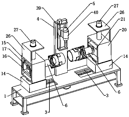
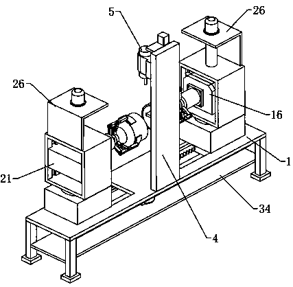
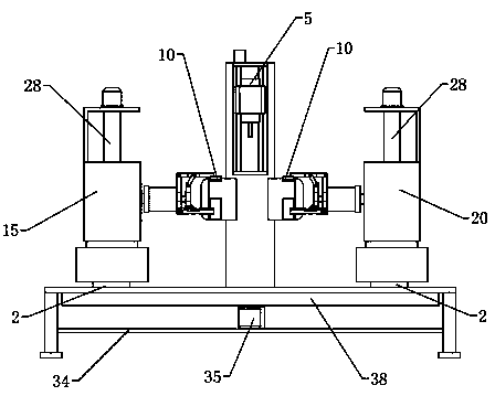
The invention relates to the technical field of steel cylinder girth welding, and specifically relates to an automatic steel cylinder girth welding device. The automatic steel cylinder girth welding device comprises an operation table, wherein an opposite driving assembly is arranged at the bottom of the operation table; the opposite driving assembly comprises two movable bottom plates; a movablenotch used for allowing each movable bottom plate to move is formed in the operation table; a rotary table is arranged at the top of each movable bottom plate; a left side rotating assembly and a right side auxiliary rotating assembly are arranged on the two rotary tables correspondingly; clamping jaw assemblies are arranged at the adjacent ends of the left side positioning rotating assembly and the right side rotating assembly correspondingly; lifting adjusting assemblies are arranged above the left side rotating assembly and the right side auxiliary rotating assembly correspondingly; a vertical support is arranged between the two clamping jaw assemblies; and a welding gun capable of lifting is arranged on the vertical support. According to the device, the height of each steel cylinder needing to be welded can be adjusted correspondingly, butt joint is automatically carried out, the height of the welding gun can be automatically adjusted, and the welding precision is improved.

Description

Technical field [0001] The invention relates to the technical field of steel cylinder circumferential seam welding, in particular to an automatic steel cylinder circumferential seam welding device. Background technique [0002] At present, the Chinese patent document with the authorized announcement number CN201900395U in the prior art discloses a liquefied petroleum gas cylinder circumferential seam welding device, including a bracket and a steel cylinder circumferential seam welding device arranged on the bracket. The steel cylinder circumferential seam welding device Including bottom welding torch and cover welding torch. The bracket is also provided with a steel cylinder clamping device, which is hinged to the bracket and connected with the rotating shaft through a key. When the rotating shaft rotates, the steel cylinder clamping device is driven to rotate. The steel cylinder clamping device is two installed on both sides of the steel cylinder. Clamps, the two clamps squeeze...

Claims


Application Information

Patent Timeline
IPC IPC(8): B23K31/02B23K37/053
CPCB23K31/02B23K37/0533
Inventor 温金建
Owner 温金建
Why Eureka
Try Eureka