Directional conveying switch valve

A valve and valve plate technology, which is used in the field of directional conveying and switching valves, can solve the problems of high requirements for power actuators, large valve plate resistance, and blocking valve plates, etc., to achieve good sealing effect, reduce jamming, and small resistance. Effect

Pending Publication Date: 2020-01-10
河南众森电力设备有限公司
View PDF1 Cites 2 Cited by
  • Summary
  • Abstract
  • Description
  • Claims
  • Application Information

AI Technical Summary

Problems solved by technology

This kind of gate valve structure bears the weight of the upper material, the resistance of the valve plate opening and closing is relatively large, and the required driving force is correspondingly relatively large, and the correspondingly select

Method used


Image

  • Directional conveying switch valve
  • Directional conveying switch valve
  • Directional conveying switch valve

Examples


Embodiment Construction

[0018] The following will clearly and completely describe the technical solutions in the embodiments of the present invention with reference to the accompanying drawings in the embodiments of the present invention. Obviously, the described embodiments are only some, not all, embodiments of the present invention. Based on the embodiments of the present invention, all other embodiments obtained by persons of ordinary skill in the art without making creative efforts belong to the protection scope of the present invention.

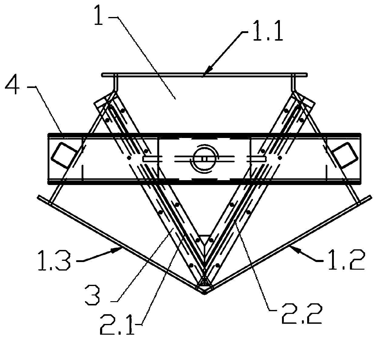
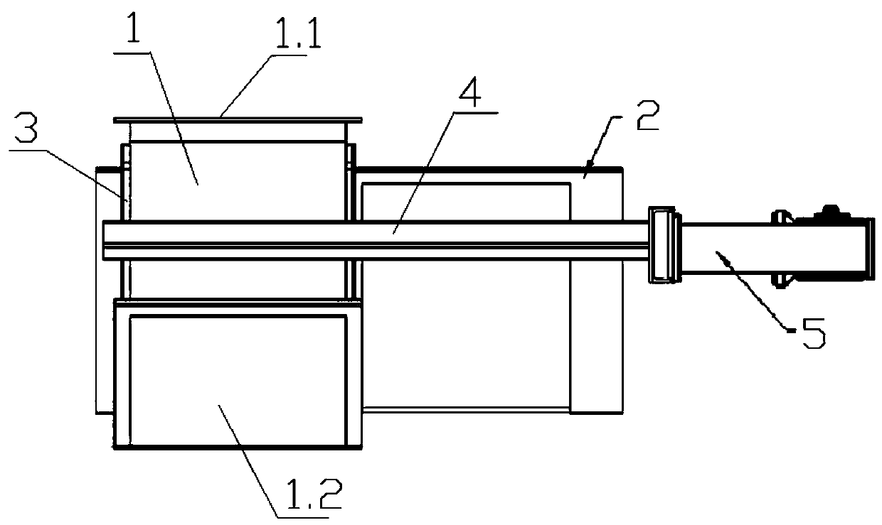
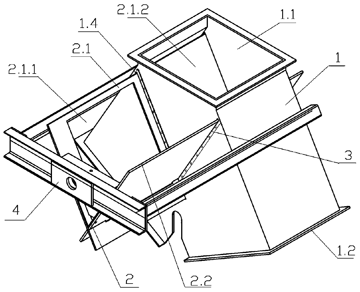
[0019] Such as figure 1 , 2 A directional conveying switching valve shown in . There is a V-shaped valve plate 2, and the two side walls of the valve body are provided with a V-shaped valve plate groove 1.4 protruding through the V-shaped valve plate. The V-shaped valve plate can reciprocate along the V-shaped valve plate groove to form the first discharge Switching between the two working positions when the second discharge port is turned on while the first...


PUM


Abstract

The invention discloses a directional conveying switch valve. The directional conveying switch valve is provided with a valve body, the valve body is provided with a material inlet, a first discharging port and a second discharging port, and the valve body is provided with a V-shaped valve plate; V-shaped plate grooves are formed in the two side walls of the valve body, the V-shaped valve plate penetrates through the V-shaped plate grooves and extends out of the V-shaped plate grooves, and the V-shaped valve plate can reciprocate along the V-shaped plate grooves, so that the first dischargingport is disconnected and the second discharging port is connected at the same time, or the first discharging port is connected and the second discharging port stops switch between the two work stations; and the valve body is fixedly connected with a support, a driving device is fixed to the support, and the V-shaped valve plate is connected to the driving device which drives the V-shaped valve plate to reciprocate. The directional conveying switch valve has the characteristics that the material flow direction is reliably switched, smooth opening and closing are achieved, flowing is not easilyblocked, and the closing effect is good. Normal discharging of an overall conveying system is guaranteed.

Description

technical field [0001] The invention belongs to the technical field of valves, and in particular relates to a directional conveying switching valve. Background technique [0002] The valves used in the traditional material conveying switch mostly adopt the flap structure. This kind of valve is mostly suitable for light materials. When the flap is used for a long time, more and more materials are glued to the flap, and the flap will jam when switching. The dead phenomenon, the flip switch is not in place, the seal is not tight, and the material leakage is easy to occur. The gate valve is also widely used in material transportation. For example, the publication date is 2014.11.05 and the publication number is CN 104132150 A. The invention discloses a new type of hydraulic split gate valve. In the horizontal chute on the wall, the inserting plate is connected to the reciprocating power mechanism. It is characterized in that: there are two inserting plates, which are arranged o...

Claims


Application Information

Patent Timeline
IPC IPC(8): B65G11/20
CPCB65G11/206
Inventor 刘纯雷丁洪超潘利
Owner 河南众森电力设备有限公司
Why Eureka
Try Eureka