Variable-diameter coiling machine

A technology of coiling machine and reel, which is applied in the direction of coiling strips, thin material processing, transportation and packaging, etc. It can solve the problems of limited reel size, inability to realize diameter change, inability to realize ultra-thin stainless steel high-precision coiling, etc. , to achieve the effect of improving work efficiency

Inactive Publication Date: 2020-01-10
SHANXI TAIGANG STAINLESS STEEL CO LTD
8 Cites 1 Cited by

AI-Extracted Technical Summary

Problems solved by technology

[0002] In the stainless steel industry, the coiling inner diameter of the usual coiler is mostly 408mm, 508mm, etc., while customers in Japan, Europe and the United States require an inner diameter of 3 inches and 6 inches, and the edge coiling effect must reach ±0.2mm. The configuration of the existing unit The gap with the above requirements is too large, only coils with an inner diameter of ...

Method used

Shown in Fig. 1 and Fig. 2, a kind of variable diameter coiler comprises frame 1, and 6 two ends of 6 inch reels are fixed on a side of frame 1 by bearing seat 10, and hole position is set on frame 1 And fixing bolts to ensure the stability of the r...

Abstract

The invention discloses a variable-diameter coiling machine, and belongs to the technical field of metallurgical machinery. The variable-diameter coiling machine comprises a rack, and is characterizedin that two ends of a 6-inch reel are fixed to one lateral side of the rack through bearing seats, the right end of the 6-inch reel extends out of the bearing seat and is connected with a motor through a coupler, and the bearing seats at the two ends of the 6-inch reel are respectively hinged to one air cylinder through a hinge lug; the two ends of a 3-inch reel are fixed to the other lateral side of the rack through bearing seats, the bearing seats at the two ends of the 3-inch reel are respectively connected with one air cylinder through a hinge lug, the bearing seats are connected with a linear sliding block, the linear sliding block is arranged on a linear guide rail and slides on the linear guide rail, and the linear guide rail is fixedly mounted on the rack. The variable-diameter coiling machine realizes the coiling of ultra-thin stainless steel belts with different inner diameters, improves the product tension precision and edge rolling uniformity precision, reduces the labor intensity of an operator, ensures the operation safety, and provides a high-level and high-precision stainless steel product for a user.

Application Domain

Webs handling

Technology Topic

Electric machinerySteel belt +5

Image

  • Variable-diameter coiling machine
  • Variable-diameter coiling machine

Examples

  • Experimental program(1)

Example Embodiment

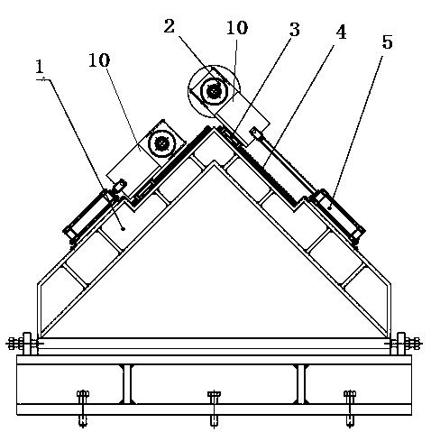
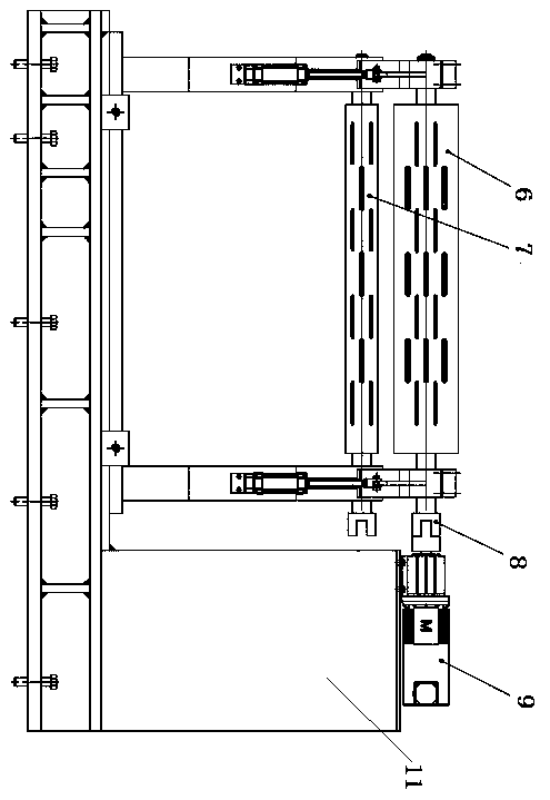
[0021] figure 1 , figure 2 As shown, a variable diameter coiler includes a frame 1. Both ends of a 6-inch reel 6 are fixed on one side of the frame 1 through a bearing seat 10. The frame 1 is provided with holes and fixing bolts to ensure that the reel is working stability in the state. The right end of the 6-inch reel 6 extends out of the bearing seat 10 and is connected to the motor 9 through the coupling 8 .
[0022] Both ends of the 3-inch reel are fixed on the other side of the frame 1 through the bearing seat 10, and the bearing seats at both ends of the 3-inch reel 7 are connected to a cylinder 5 through hinge ears. When the reel is replaced, the cylinder pushes the spare reel into the working position.
[0023] The bearing seat is connected with the linear slide block, and the linear slide block is arranged on the linear guide rail and slides on the linear guide rail;
[0024] Linear guides are fixed on the rack.
[0025] The frame is a triangular steel structure frame with an included angle of 60 degrees, and the linear guide rails are respectively arranged on one or two sides.
[0026] The motor drives the reel to rotate to realize the establishment of tension with the uncoiler. The reel can be switched online. During production, the rubber sleeve is installed on the reel, the air pressure is input, the reel is expanded, and the steel strip can be covered at this time.
[0027] The frequency converter and inverter cabinet are arranged in the electrical room, and the PLC program is written into the rewinding unit system to connect with the main program of the rewinding unit. By modifying the corresponding hardware configuration and software program in STEP7, increase the tension control program of this coiler, and carry out the debugging of friction force and dynamic compensation.
[0028] The three reels are arranged in an equilateral triangle, and the two reels are controlled by two cylinders respectively.
[0029] The coupling is a one-word coupling. After the motor rotates to the "waiting-to-roll" position, the cylinder pushes the reel in, and the coupling is automatically docked, so that the reel and the motor can be connected online without disassembling the coupling and motor, so as to realize fast online change of the reel.
[0030] In the "3-inch reel" mode, the coupling first rotates to the 6-inch reel position, and then the 6-inch reel exits. At this time, the coupling rotates to the 3-inch reel position and the 3-inch reel enters. This process and logic are completed by the PLC control motor and pneumatic system. The rotation position of the coupling and the working position of the reel are provided with feedback information by the limit switch.

PUM

no PUM

Description & Claims & Application Information

We can also present the details of the Description, Claims and Application information to help users get a comprehensive understanding of the technical details of the patent, such as background art, summary of invention, brief description of drawings, description of embodiments, and other original content. On the other hand, users can also determine the specific scope of protection of the technology through the list of claims; as well as understand the changes in the life cycle of the technology with the presentation of the patent timeline. Login to view more.

Similar technology patents

Automatic device for welding and detecting lithium battery

ActiveCN103904367AShorten the running distanceImprove work efficiency
Owner:DONGGUAN HONBRO LI BATTERY EQUIP TECH

Vacuum cleaner

InactiveCN103356140Aprevent liftingImprove work efficiency
Owner:SUZHOU HAAN TECH +1

Classification and recommendation of technical efficacy words

  • Improve work efficiency

Cooperation service platform facing different source data

InactiveCN101174957AImprove management level and qualityImprove work efficiency
Owner:NANJING UNIV OF FINANCE & ECONOMICS

Screw drilling tool, vertical drilling tool testing method and well inclination simulation testing equipment

InactiveCN111594144AReduced height requirementsImprove work efficiency
Owner:DEZHOU UNITED GASOLINEEUM MACHINERY

Method for intelligent automatic identification of transmission circuit parts

Owner:INFORMATION COMM COMPANY STATE GRID SHANDONG ELECTRIC POWER +2

Keyboard spill-proofing mechanism

ActiveUS7030330B2minimize manufacturing costimprove work efficiency
Owner:LITE ON SINGAPORE PTE LTD
Why Eureka
Try Eureka