Connecting structure of prefabricated column and superposed beam as well as construction method of connecting structure

A technology for connecting structures and prefabricated columns, which is applied in the direction of building construction and construction, can solve the problems of inconvenient construction and low tolerance, and achieve the effects of easy and adjustable installation, complete force transmission path, and reduced number of supporting forms

Pending Publication Date: 2020-01-10
筑友智造科技产业集团有限公司
View PDF2 Cites 3 Cited by
  • Summary
  • Abstract
  • Description
  • Claims
  • Application Information

AI Technical Summary

Problems solved by technology

[0004] The object of the present invention is to provide a connection structure between prefabricated columns and composite beams and its construction method. The present invention designs a joint connection method, which is intended to solve the common problems in the existing connection structures between prefabricated columns and beams. , such as low tolerance, inconvenient construction, etc., and can effectively improve construction efficiency and shorten the construction period; at the same time, ensure the mechanical properties of the joints and the repairability after the earthquake

Method used


Image

  • Connecting structure of prefabricated column and superposed beam as well as construction method of connecting structure
  • Connecting structure of prefabricated column and superposed beam as well as construction method of connecting structure
  • Connecting structure of prefabricated column and superposed beam as well as construction method of connecting structure

Examples


Embodiment 1

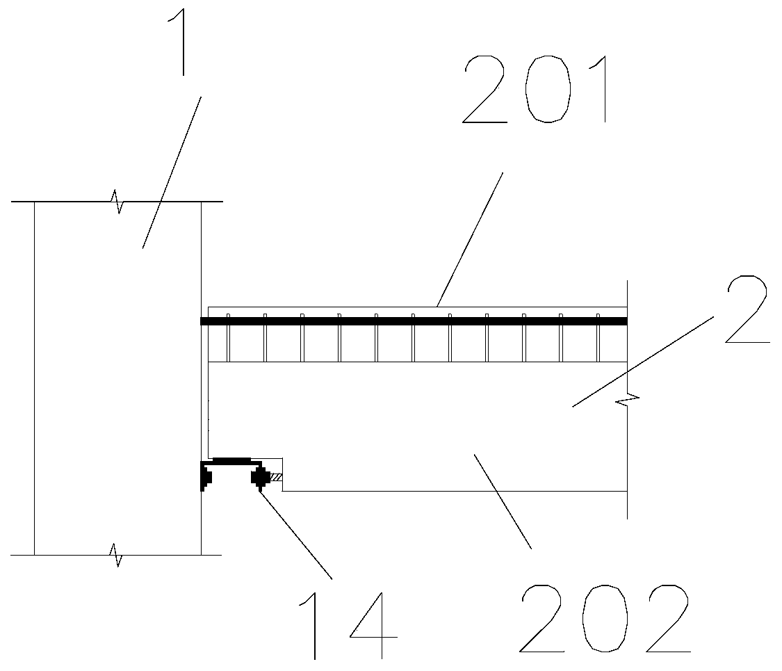
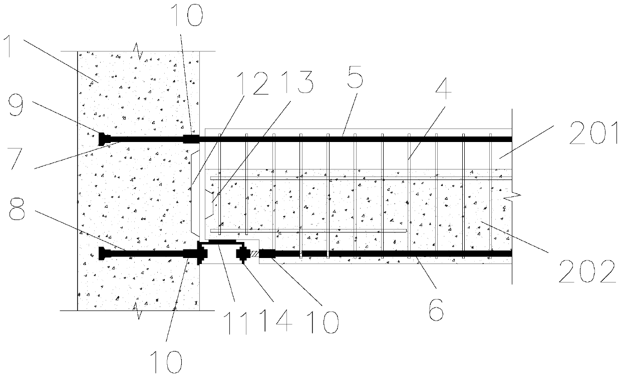
[0053] Reference attached figure 1 As shown, this embodiment is a connection structure between a prefabricated column 1 and a composite beam 2 , and the composite beam 2 includes a prefabricated part 201 and a cast-in-place part 202 . The height of the prefabricated column 1 exceeds the height of one floor. In this embodiment, it is a prefabricated column 1 with a height of 3 floors. In other embodiments, prefabricated columns 1 with a height of 1-2 floors can also be used. Prefabricated columns 1 in height between 3 storeys. The end of the composite beam 2 is connected to the side of the precast column 1, the precast column 1 is connected to the lower longitudinal reinforcement 6 in the cast-in-place part 202 through the longitudinal reinforcement connection assembly 14, and the upper longitudinal reinforcement 5 in the cast-in-place part 202 is connected to the precast column 1 For connection, the distance between the upper longitudinal rib 5 and the top surface of the pref...

Embodiment 2

[0070] This embodiment is the connection structure between the prefabricated column 1 and two composite beams 2, refer to the attached Figure 5 As shown, when the composite beams 2 are arranged on both sides of the prefabricated column 1, the connection structure on each side is roughly the same as that in Embodiment 1. The difference is that both ends of the upper transverse anchoring rib 7 in the prefabricated column 1 are provided with first sleeves 10, both ends of the lower transverse anchoring rib 8 are provided with second sleeves 10, and the first sleeve 10 and the second sleeve 10 are both anchored in the concrete of the prefabricated column 1 , and the end surface of the sleeve 10 is slightly lower than or flush with the side surface of the precast column 1 .

[0071] In the improved solution of this embodiment, the upper transverse anchor bars 7 and the lower transverse anchor bars 8 can be provided with anchor plates or anchor legs or anchor nets to enhance the an...

Embodiment 3

[0074] Reference attached Image 6 As shown, the difference between the connection structure of prefabricated columns 1 and composite beams 2 in this embodiment and this embodiment 1 is that a prefabricated exterior wall panel 3 is also provided on the outdoor side of the column-beam structure in embodiment 5. The prefabricated exterior wall panel 3 is fixed to the composite beam 2 through connectors, and the height of the top side of the prefabricated exterior wall panel 3 is slightly higher than or flush with the top side of the cast-in-place part 202 of the composite beam 2, so the height of the poured composite beam 2 When the concrete of the part 202 is poured in place, the top side of the prefabricated exterior wall panel 3 can serve as an outer formwork, which reduces the workload of formwork erection and improves construction efficiency.

[0075] The difference between the construction method in this embodiment and Embodiment 1 is that: between steps S4 and S5, there i...


PUM


Abstract

The invention provides a connecting structure of a prefabricated column and a superposed beam. The connecting structure comprises the prefabricated column and the superposed beam, wherein the superposed beam comprises a prefabricated part and a cast-in-place part; the end head of the superposed beam is connected with the side surface of the prefabricated column, the upper end surface of the prefabricated column is higher than a stirrup at the top side of the prefabricated part, a lower longitudinal rib in the cast-in-place part is connected with the prefabricated column through a longitudinalsteel bar connecting assembly, and an upper longitudinal rib in the cast-in-place part is connected with the prefabricated column. The invention further provides a construction method of the connecting structure, which comprises the following steps that S1, the prefabricated column is hoisted and positioned; S2, one side of the longitudinal steel bar connecting assembly is connected with the prefabricated column, and a vertical support is arranged; S3, the superposed beam prefabricated part is hoisted and positioned; S4, the longitudinal steel bar connecting assembly is connected with the superposed beam prefabricated part, and a formwork at the joint of the prefabricated part and the prefabricated column is built; and S5, concrete is poured into the cast-in-place part. The connecting structure has the advantages that the tolerance capability is better, steel bar force transmission path at the top and bottom is complete, and connecting parts can be replaced after the earthquake occurs.

Description

technical field [0001] The invention belongs to the field of prefabricated buildings, and in particular relates to a connection structure of prefabricated columns and composite beams and a construction method thereof. Background technique [0002] The connection methods between prefabricated columns and beams in the prior art are mainly divided into cast-in-place connection and pure dry connection. For the cast-in-place connection method, the example in the prefabricated building code is mainly used. The composite beam is erected on the top of the prefabricated column, and then the formwork is set to pour the top side concrete of the composite beam and the prefabricated column. The disadvantage of this structure is that: since the scaffolding is generally not set up on the outside of the building during the construction of the prefabricated building, and the formwork of the cast-in-place part on the top side of the prefabricated column needs to be set up on site, it is incon...

Claims


Application Information

Patent Timeline
Patent Type & Authority Applications(China)
IPC IPC(8): E04B1/20E04B1/21
CPCE04B1/20E04B1/21
Inventor 俞大有施明哲刘彦
Owner 筑友智造科技产业集团有限公司
Why Eureka
Try Eureka