Small turbine engine rotor bearing and lubricating integrated structure

A technology of turbine engine and rotor support, applied in the direction of engine components, machines/engines, mechanical equipment, etc., can solve the problems of cumbersome lubrication system and complex structure, and achieve the effect of enhancing heat exchange effect, ensuring smooth operation and stable elastic support effect. Effect

Active Publication Date: 2020-01-10
SICHUAN AEROSPACE ZHONGTIAN POWER EQUIP CO LTD
View PDF5 Cites 6 Cited by
  • Summary
  • Abstract
  • Description
  • Claims
  • Application Information

AI Technical Summary

Problems solved by technology

[0005] Based on the above problems, the present invention provides a small turbine engine rotor supporting and lubricating integrated structure, which solves the problems of the existing small turbine engine's complicated supporting structure and heavy lubrication system, and realizes the highly integrated elastic support and lubricating oil internal circulation of the small turbine engine and efficient heat transfer

Method used


Image

  • Small turbine engine rotor bearing and lubricating integrated structure
  • Small turbine engine rotor bearing and lubricating integrated structure

Examples


Embodiment 1

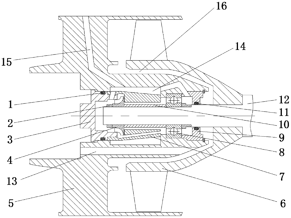
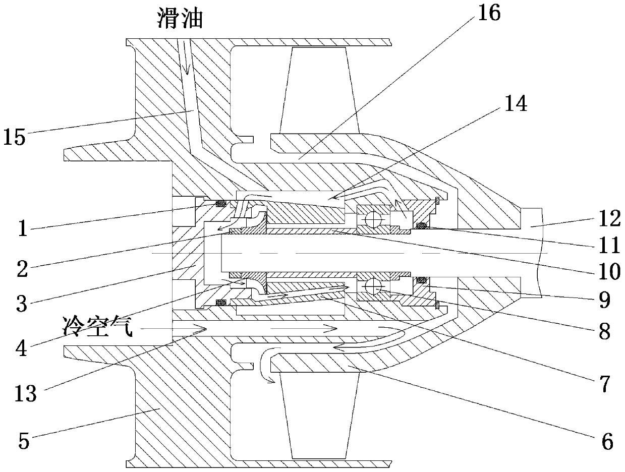
[0030] see Figure 1~2 , a small turbine engine rotor supporting and lubricating integrated structure, including a casing 5, an engine shaft 12 is installed on the casing 5, and a lock nut 2, a closed centrifugal pump 4, and a positioning sleeve 10 are sequentially arranged in series on the engine shaft 12. The bearing 8, the rear blocking cover 9 and the rotor impeller 6, the side of the lock nut 2 away from the rear blocking cover 9 is provided with the front blocking cover 3 connected with the casing 5, and the front blocking cover 3, the casing 5, and the rear blocking cover 9 are sealed and connected, and the casing 5 on the outside of the engine shaft 12 is provided with a strip groove 13. The position where the bearing 8 is installed on the casing 5 and the side wall of the casing 5 are in the form of a cantilever. The front block cover 3 and the rear block cover 9. The closed space formed by the casing 5 is provided with a guide block 7 connecting the closed centrifuga...

Embodiment 2

[0037] This embodiment is further optimized on the basis of implementation 1, specifically:

[0038] The front rubber ring 1 is used for sealing between the front blocking cover 3 and the casing 5, and the rear rubber ring 11 is used for sealing between the rear blocking cover 9 and the casing 5. The design of the front rubber ring 1 makes the connection between the front blocking cover 3 and the casing 5 tighter, avoiding the leakage of the side oil of the front cover, and the design of the rear end cover makes the connection between the dog end cover and the casing 5 tighter. Tight, avoiding the leakage of the side slip oil of the rear end cover.

[0039] As a preferred mode, the engine shaft 12 runs through the casing 5 transversely, one end of the engine shaft 12 is connected with the lock nut 2, the other side of the engine shaft 12 is connected with the rotor impeller 6, and the casing on the side of the rotor impeller 6 is connected. 5 is provided with an annular groov...


PUM


Abstract

The invention relates to the technical field of turbine engines, and discloses a small turbine engine rotor bearing and lubricating integrated structure. The structure comprises a casing, an engine rotating shaft, a locking nut, a closed type centrifugal pump, a positioning sleeve, a bearing, a rear plug cover, a front plug cover and a rotor impeller are arranged on the casing, a strip groove is formed in the casing, a structure, for mounting the bearing, of the casing and the side wall of the casing are in a cantilever manner, a guide block connected with the closed type centrifugal pump andthe bearing is arranged in sealed space formed by the front plug cover, the rear plug cover and the casing, an inner cavity way is formed in seal space formed by the front plug cover, the rear plug cover and the casing, the inner cavity way can communicate with an inlet and outlet of the closed type centrifugal pump and penetrates through the guide block to be connected with the closed type centrifugal pump and the rotating shaft to form an inner circulation oil way, and a slide oil injection hole is formed in the casing. The problems that an existing small turbine engine bearing structure iscomplex, and a lubricating system is heavy are solved, and high integration of elastic bearing and slide oil inner circulation of a small turbine engine and the efficient heat exchange effect are achieved.

Description

technical field [0001] The invention relates to the technical field of turbine engines, in particular to a small turbine engine rotor supporting and lubricating integrated structure. Background technique [0002] Small turbine engine rotors generally have high speed and load, and because the engine emphasizes small windward area and large unit thrust index, the volume space of the rotor's support and lubrication structure is repeatedly compressed, so high integration and efficient support and lubrication It has an important influence on the indicators of the turbine engine. [0003] The rotor support of the turbine engine requires reasonable stiffness and deflection, which can be used to adjust the critical speed and suppress vibration. The lubrication structure of the rotor needs to provide effective lubrication and cooling for the bearings to avoid bearing wear and overheating lock failures; general turbine engines When designing the supporting structure, install elastic ...

Claims


Application Information

Patent Timeline
Patent Type & Authority Applications(China)
IPC IPC(8): F01D25/24F01D25/28F01D25/18F01D25/20F01D25/16F01D25/14F01D25/12F01D11/00
CPCF01D11/003F01D25/12F01D25/14F01D25/16F01D25/18F01D25/20F01D25/24F01D25/28
Inventor 孟春潮刘驰李芳宋勇何国忠李纪永
Owner SICHUAN AEROSPACE ZHONGTIAN POWER EQUIP CO LTD
Why Eureka
Try Eureka