Micro-miniature under-pressure pluggable fluid connector

A micro-miniature, connector technology, applied in couplings, mechanical equipment, etc., can solve problems such as seal failure, detachment spring, fast speed, etc., to reduce flow resistance, improve fluid flux, and improve stability.

Active Publication Date: 2020-01-10
CHINA AVIATION OPTICAL-ELECTRICAL TECH CO LTD
View PDF10 Cites 5 Cited by
  • Summary
  • Abstract
  • Description
  • Claims
  • Application Information

AI Technical Summary

Problems solved by technology

[0004] 1. The size of the O-ring of the miniature fluid connector is small, and the O-ring is easily washed out during the plugging and unplugging process, resulting in seal failure
[0005] 2. Due to the size limitation of micro-miniature fluid connectors, adding an O-ring protection sleeve structure will affect the flow performance of the connector
However, in actual use, it is found that the structure of using a separate sealing block and spring is not stable. Due to the fast internal liquid circulation and strong impact force when the connector is working, it will continuously impact the sealing block set in the center of the fluid channel through the spring. In addition, the sealing block needs to form a liquid channel with the plug housing, so the sealing block does not contact the inner wall of the plug housing, which provides space for the radial displacement of the sealing block under the action of external force
The above comprehensive factors may cause the sealing block to be impacted by high-speed liquid, causing its radial displacement or even breaking away from the spring

Method used


Image

  • Micro-miniature under-pressure pluggable fluid connector
  • Micro-miniature under-pressure pluggable fluid connector
  • Micro-miniature under-pressure pluggable fluid connector

Examples


Embodiment Construction

[0030] The technical solutions of the present invention will be further described in detail below in conjunction with the accompanying drawings and preferred embodiments.

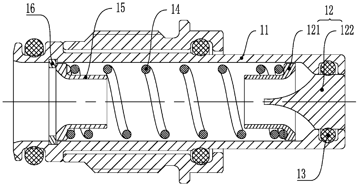
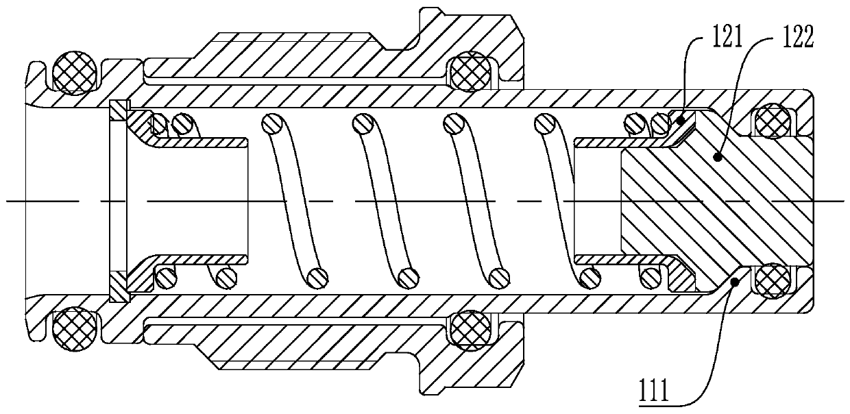
[0031] see Figure 1 to Figure 6 , a micro-miniature pressurized plug-in fluid connector, including a plug and a socket adapted to the plug, the front ends of the plug and the socket are socket ends, and the plug includes a plug housing 11, a sealing assembly 12, a first sealing ring 13. The first spring 14 and the positioning sleeve 15, the sealing assembly 12 is slidably assembled on the front end of the plug housing 11, the sealing assembly 12 includes a sleeve 121 and a sealing block 122 inserted in the front end of the sleeve; the rear end of the positioning sleeve 15 The first retaining ring 16 is fixed on the inner rear end of the plug housing 11, one end of the first spring 14 is in contact with the sleeve 121, and the other end is in contact with the end face of the positioning sleeve 15, and the f...


PUM


Abstract

The invention provides a micro-miniature under-pressure pluggable fluid connector. The micro-miniature under-pressure pluggable fluid connector comprises a plug and a socket. The plug comprises a plugshell and a sealing assembly. The sealing assembly comprises a sleeve and a sealing block. A locating sleeve is arranged at the rear end of the plug shell. The locating sleeve abuts against the sleeve through a first spring. The inner wall of the front end of the plug shell is provided with a first limiting part. A first seal ring is arranged between the sealing block and the plug shell. The socket comprises a socket shell and a sealing rod assembled in the socket shell. The sealing rod is sleeved with a second spring and a sealing ring. The front end of the second spring abuts against the sealing ring, and the rear end of the second spring abuts against the sealing rod. The inner wall of the front end of the socket shell is provided with a second limiting part. The inner side of the sealing ring and the sealing rod form sealing through a second seal ring. The front end of the sealing rod is provided with a plurality of through holes. During operation of the micro-miniature under-pressure pluggable fluid connector, no any seal ring is exposed in fluid, so that the seal rings are prevented from being washed away; and moreover, through the special sealing assembly, the stability ofthe connector is improved, the flow resistance of fluid is reduced, and the fluid flux is increased.

Description

technical field [0001] The invention belongs to the technical field of fluid connectors, in particular to a miniature pressurized plug fluid connector. Background technique [0002] With the continuous development of high-frequency, high-density, and high-integration electronic components in equipment, the problem of how to achieve efficient heat dissipation for equipment is becoming more and more prominent. Liquid cooling technology has become the first choice to solve this problem. Liquid cooling technology has been widely used in aviation, aerospace, electronics, ships, communications, wind power, electric vehicles and other fields. [0003] With the development of technology, electronic equipment tends to be miniaturized, and there is an urgent need for micro-miniature fluid connectors to realize the transmission of fluid between the cooled module and the chassis, but such existing connectors have the following problems during operation: [0004] 1. The size of the O-ri...

Claims


Application Information

Patent Timeline
Patent Type & Authority Applications(China)
IPC IPC(8): F16L37/32
CPCF16L37/32
Inventor 赵颍杰杨安礼马乐
Owner CHINA AVIATION OPTICAL-ELECTRICAL TECH CO LTD
Why Eureka
Try Eureka