Three-dimensional laser scanning calibration method simultaneously constrained by point and surface characteristics

A three-dimensional laser and surface feature technology, applied in the direction of using optical devices, measuring devices, instruments, etc., can solve the problems of consuming manpower and material resources, lack of angle or orientation constraints, and less joint adjustment

Active Publication Date: 2020-01-10
SHANGHAI INST OF TECHNICAL PHYSICS - CHINESE ACAD OF SCI
View PDF9 Cites 2 Cited by
  • Summary
  • Abstract
  • Description
  • Claims
  • Application Information

AI Technical Summary

Problems solved by technology

[0003] According to the shape characteristics of the reference target in the calibration process, the calibration methods that have appeared successively include: ①Surface-based calibration, which can conveniently select the reference datum plane on site and easily obtain a large number of redundant observations; but only provides one-dimensional Direction constraints, that is, the condition of the minimum distance from the point to the plane, lack of angle or orientation constraints, usually suitable for sparse point cloud situations
②Point-based calibration can effectively detect the deviation of the distance and the three-dimensional direction of two angles, but it needs to be evenly arranged and accurately measure a large number of point targets, which consumes manpower and material resources, and is generally suitable for dense point cloud situations
In addition, the calibration method of the 3D laser scanner constrained by point and surface features has not been reported yet, and the joint adjustment using multiple features is still rare

Method used


Image

  • Three-dimensional laser scanning calibration method simultaneously constrained by point and surface characteristics
  • Three-dimensional laser scanning calibration method simultaneously constrained by point and surface characteristics
  • Three-dimensional laser scanning calibration method simultaneously constrained by point and surface characteristics

Examples


Embodiment Construction

[0046] The embodiments of the present invention are described in further detail below, but the embodiments are not limited to the present invention, and all similar methods and similar changes of the present invention should be included in the protection scope of the present invention.

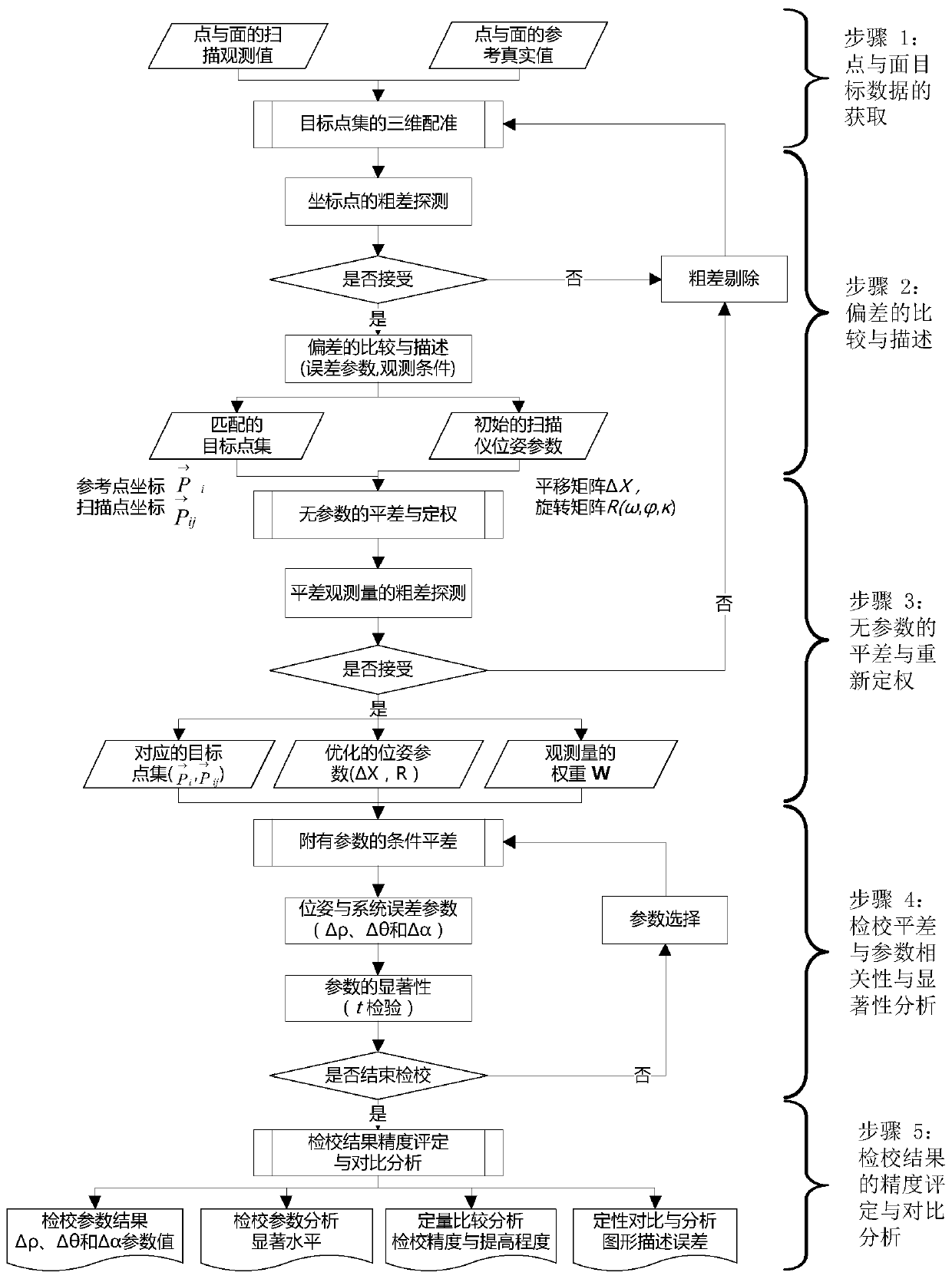
[0047] (1) Simultaneously obtain the scanning observation values ​​and reference real values ​​of point and surface characteristic targets, and perform three-dimensional registration of target point sets and gross error detection of coordinate points; simultaneously arrange characteristic targets of point and surface targets in the laboratory, and establish a The indoor comprehensive calibration field of the 3D laser scanner, where the point-shaped target adopts a standard ball with a diameter of 10cm, the laser-printed black background and white circle marks with a diameter of 14cm and 5cm, and black and white diagonally distributed marks. Off-white planed wood boards with a width of 1.0m and ...


PUM


Abstract

The invention relates to a three-dimensional laser scanning calibration method simultaneously constrained by point and surface characteristics. The method comprises the following steps of (1) acquiring scanning observation values and reference true values of point and surface targets and carrying out three-dimensional registration and gross error detection on two target point sets, (2) taking a registration conversion parameter as an initial pose parameter and describing a systematic deviation between an observed value and a reference value by adopting an error model, (3) setting a system error parameter to be zero and carrying out least square estimation on the system error parameter and the initial pose parameter to obtain an optimized pose parameter and an observed quantity weight, (4)performing optimal estimation on the system error parameter and the pose parameter by using a parameter condition adjustment model with parameters and with a point and a surface as constrain conditions, and (5) correcting the scanning observation value by using the estimated parameters, counting a deviation between the observation value and the reference value before and after correction by usingmathematics, and evaluating improvement precision and degree. Compared with an existing method, the method of the invention has the advantages that various constraints are integrated, all parameters are optimally estimated at the same time, the accuracy is good, the precision is high, and the operation is easy.

Description

technical field [0001] The invention relates to a calibration method for a three-dimensional laser scanner, especially a three-dimensional laser scanner for dense point cloud imaging. At the same time, the high-precision coordinates of the reference point and the surface feature target are compared by comparing the deviation between the scanner observation value and the reference value. A calibration method for detecting, estimating, and correcting systematic errors in scanner observations. Background technique [0002] 3D laser scanning is a non-contact active measurement technology, which can quickly obtain accurate and dense 3D discrete point coordinates (point cloud data) on the surface of an object through pulsed or phased laser ranging and instantaneous deflection angle. copy". And according to the position and attitude of the scanner, the three-dimensional space coordinates in the external coordinate system are obtained through space coordinate transformation; it pro...

Claims


Application Information

Patent Timeline
Patent Type & Authority Applications(China)
IPC IPC(8): G01B11/24G01S7/497
CPCG01B11/24G01B21/045G01S7/497
Inventor 刘向锋舒嵘谢锋徐卫明王凤香刘智慧张长兴刘成玉
Owner SHANGHAI INST OF TECHNICAL PHYSICS - CHINESE ACAD OF SCI
Why Eureka
Try Eureka