Locomotive main transformer oil tank design method and strength simulation analysis method

A technology for main transformer and simulation analysis, applied in the field of locomotive main transformer oil tank design method and strength simulation analysis, can solve problems such as calculation result deviation, achieve the effect of ensuring accuracy and simplifying the calculation process

Active Publication Date: 2020-01-10
CRRC DALIAN CO LTD
View PDF2 Cites 2 Cited by
  • Summary
  • Abstract
  • Description
  • Claims
  • Application Information

AI Technical Summary

Problems solved by technology

However, when the fuel tank bears the acceleration load in a certain direction, since the body and the side wall of the fuel tank are connected by frictional contact, the support on the side wall of the fuel tank in the opposite direction does not actually bear the inertial force of the transformer body, that is, the body and the side wall of the oil tank are in contact with each other. The support on the side wall of the fuel tank is actually a separation trend, and the direct beam element method cannot simulate this state, which leads to the deviation of the calculation results

Method used


Image

  • Locomotive main transformer oil tank design method and strength simulation analysis method
  • Locomotive main transformer oil tank design method and strength simulation analysis method
  • Locomotive main transformer oil tank design method and strength simulation analysis method

Examples


Embodiment

[0055] -- Entity model creation

[0056] The three-dimensional solid model of the main transformer of a certain type of locomotive is established by using the CAD software Creo.

[0057] -- Finite element meshing

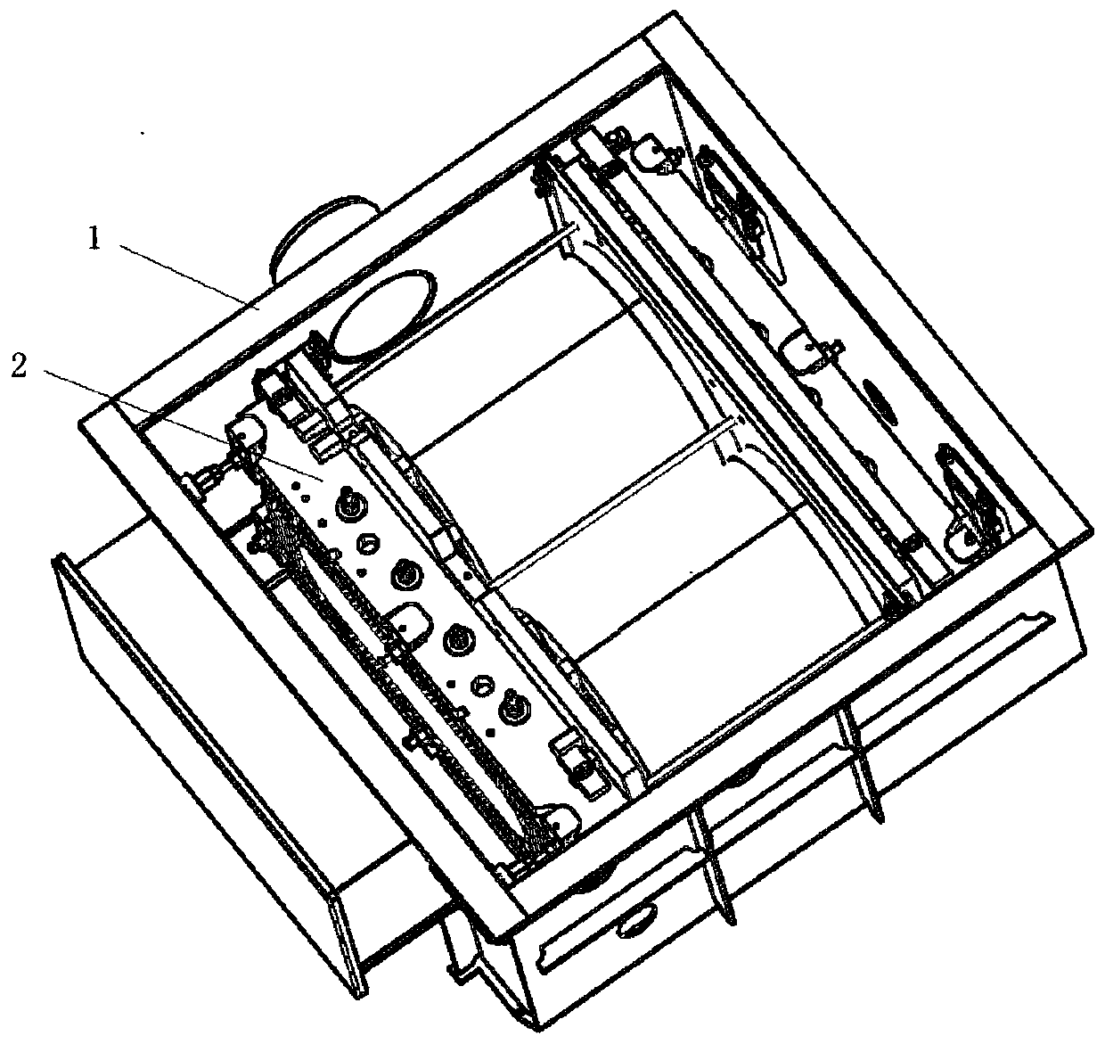
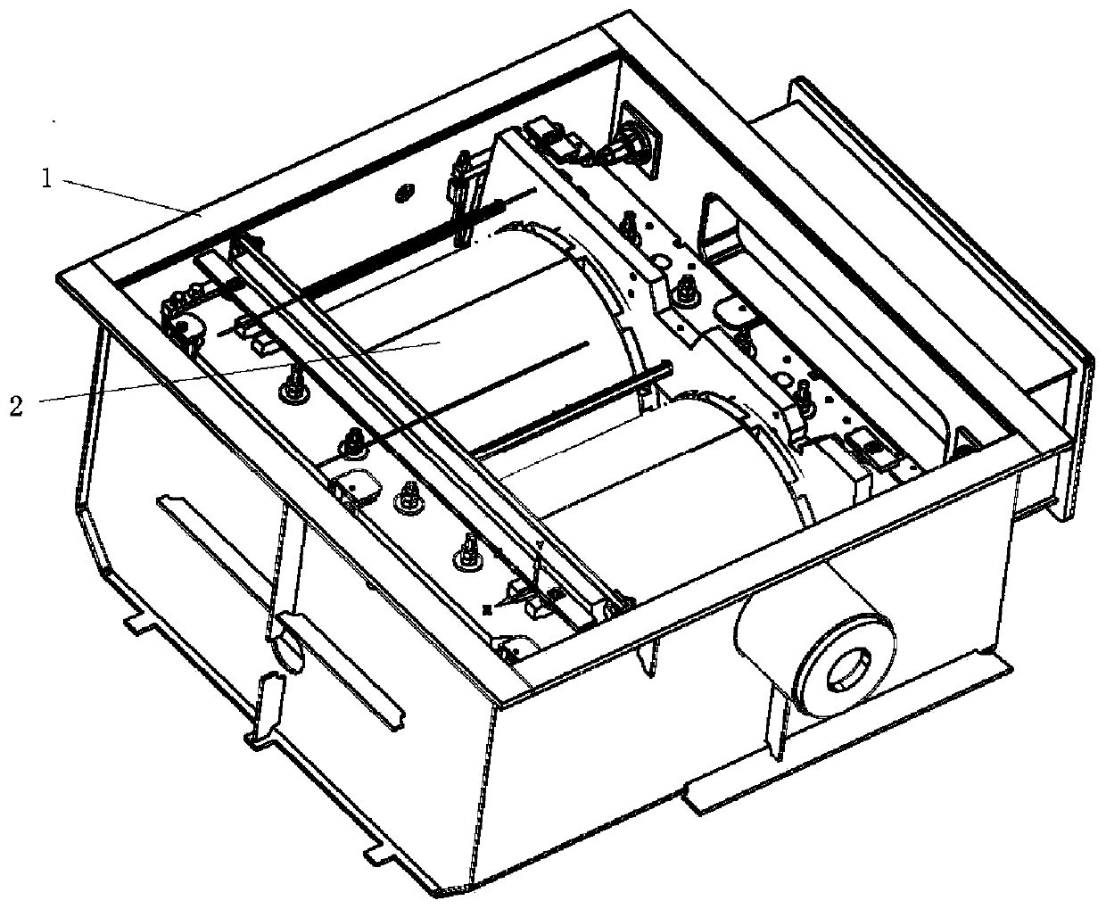
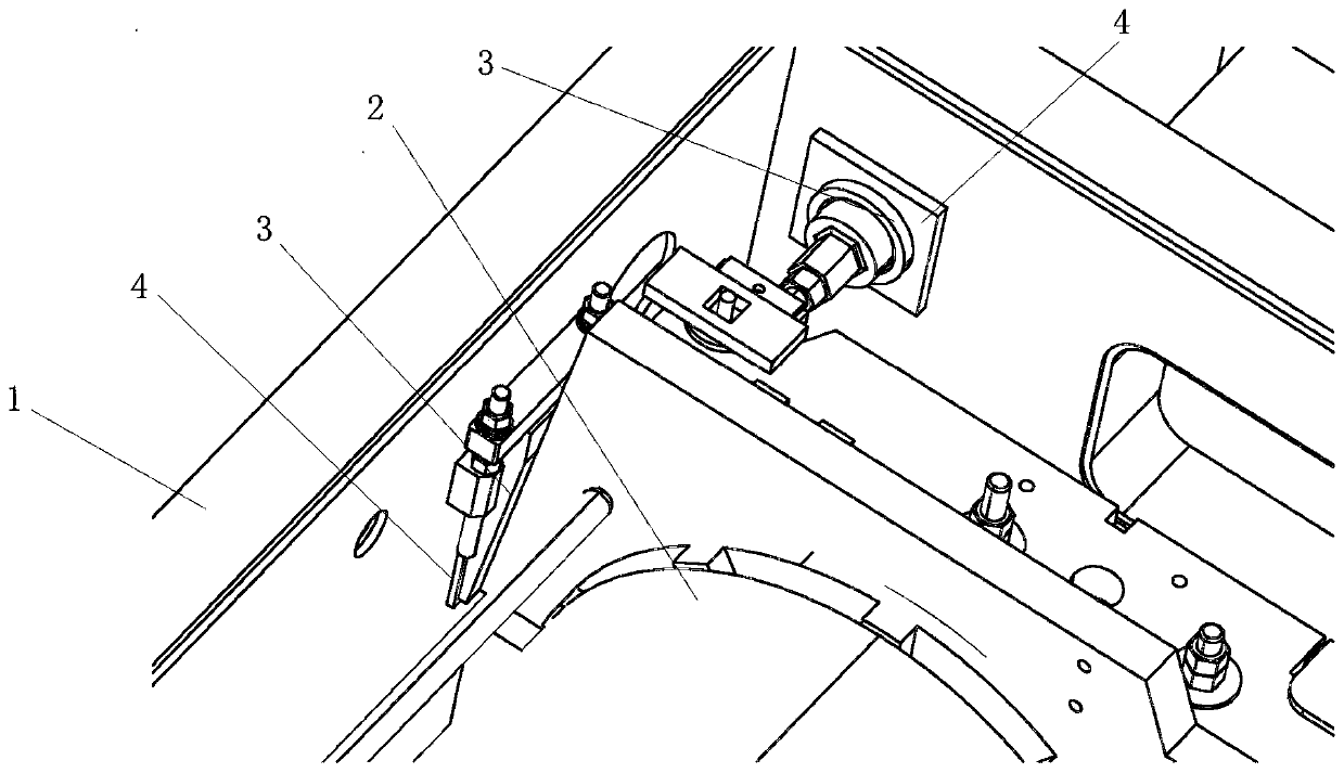
[0058] Import ANSYS Workbench finite element analysis software, after extracting the mid-plane of fuel tank body 1 and tank cover 5, use plate and shell elements to mesh the model. The block 3 and the seat plate 4 are meshed with solid elements. -- body 2 simulation

[0059] (1) The body 2 is simplified as a rigid body as a whole. For a schematic diagram of the connection relationship between the body 2 and the fuel tank body 1 and the tank cover 5, see Figure 1 to Figure 5. Among them, the seat plate 4 is welded on the box body 1 or the box cover 5; between the spacer 3 and the body 2, and between the spacer 3 and the seat plate 4 are frictional contact connections; the body 2 is fixed on the body through the spacer 3 Inside the fuel tank body 1; the tank co...


PUM


Abstract

The invention discloses a locomotive main transformer oil tank strength simulation analysis method and design method. The method comprises: establishing a solid model of a transformer body and an oiltank; performing mesh generation in ANSYS Workbench finite element analysis software; simulating the transformer body and the oil tank to obtain a simulation structure; and applying a load to the simulation structure and performing calculation and analysis to obtain an analysis result. According to the method, finite element mesh generation is carried out in ANSYS Workbench finite element analysissoftware, loads are applied to a simulation structure for analysis, the accuracy of strength simulation analysis of the locomotive main transformer oil tank is guaranteed, and a mass point and a cushion block are connected in a binding contact pair mode to be simulated into an overall structure. The cushion block of the overall structure is in friction contact connection with the oil tank, the supporting effect of the transformer body on the tank cover and the side wall of the tank body of the oil tank can also be simulated in the vacuumizing state, the calculation process is simplified, andwhen the oil tank bears the acceleration load in a certain direction, the separation trend in the reverse direction can also be simulated.

Description

technical field [0001] The invention relates to the technical field of locomotive design, in particular to a method for designing an oil tank of a main transformer of a locomotive and a strength simulation analysis method. Background technique [0002] The main transformer of some types of locomotives is pre-installed on the chassis of the locomotive body with bolts through the mounting beam, and the transformer body and auxiliary equipment are placed in the oil tank. On the one hand, the transformer body is located on the tank bottom of the fuel tank through a support, and on the other hand, it is connected to the four side walls of the fuel tank through disc-shaped, wedge-shaped and other supports. Thereby, the body of the device can be completely constrained by the tank bottom and four side walls of the fuel tank, and there is a frictional contact connection relationship between them. [0003] In order to ensure the safety of the oil tank of the locomotive's main transfo...

Claims


Application Information

Patent Timeline
Patent Type & Authority Applications(China)
IPC IPC(8): G06F30/23
CPCY02T90/00
Inventor 郑长国桂安富刘圳芮斌刘舒轶赵睿
Owner CRRC DALIAN CO LTD
Why Eureka
Try Eureka