
Coil making and winding machine for transformer manufacturing process

A transformer and winding machine technology, applied in the field of transformer manufacturing, can solve problems such as coil winding failure, unqualified coil winding, and lower productivity, so as to avoid scratches or even breakage, improve winding pass rate, and reduce waste. The effect of line crossing

Active Publication Date: 2021-03-09
威海众成电子有限公司
View PDF8 Cites 0 Cited by
  • Summary
  • Abstract
  • Description
  • Claims
  • Application Information

AI Technical Summary

Problems solved by technology

[0004] (1) When the existing transformer manufacturing equipment is winding, because the number of turns of the coil winding is large when the transformer coil is wound, and the coil winding is relatively tight, it is easy to cause deformation or even breakage of the transformer skeleton after winding, thus Lead to unqualified coil winding and reduce productivity;
[0005] (2) When the existing transformer manufacturing equipment is winding, because the coil wires need to be tight and uniform, it is easy to appear crossing, knotting and sinking from the upper layer to the next layer during the coil winding process, resulting in the coil Unqualified winding;
[0006] (3) Due to the thin insulation layer of the enameled wire, the existing transformer manufacturing equipment is easy to scratch or even break the enameled wire during winding, resulting in coil winding failure and reduced productivity

Method used


Image

  • Coil making and winding machine for transformer manufacturing process
  • Coil making and winding machine for transformer manufacturing process
  • Coil making and winding machine for transformer manufacturing process

Examples


Embodiment Construction

[0035] In order to make the technical means realized by the present invention, creative features, goals and effects easy to understand, the following combination Figure 1 to Figure 11 , to further elaborate the present invention.

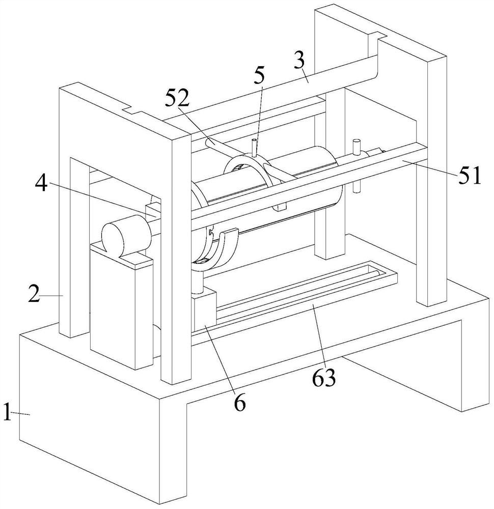
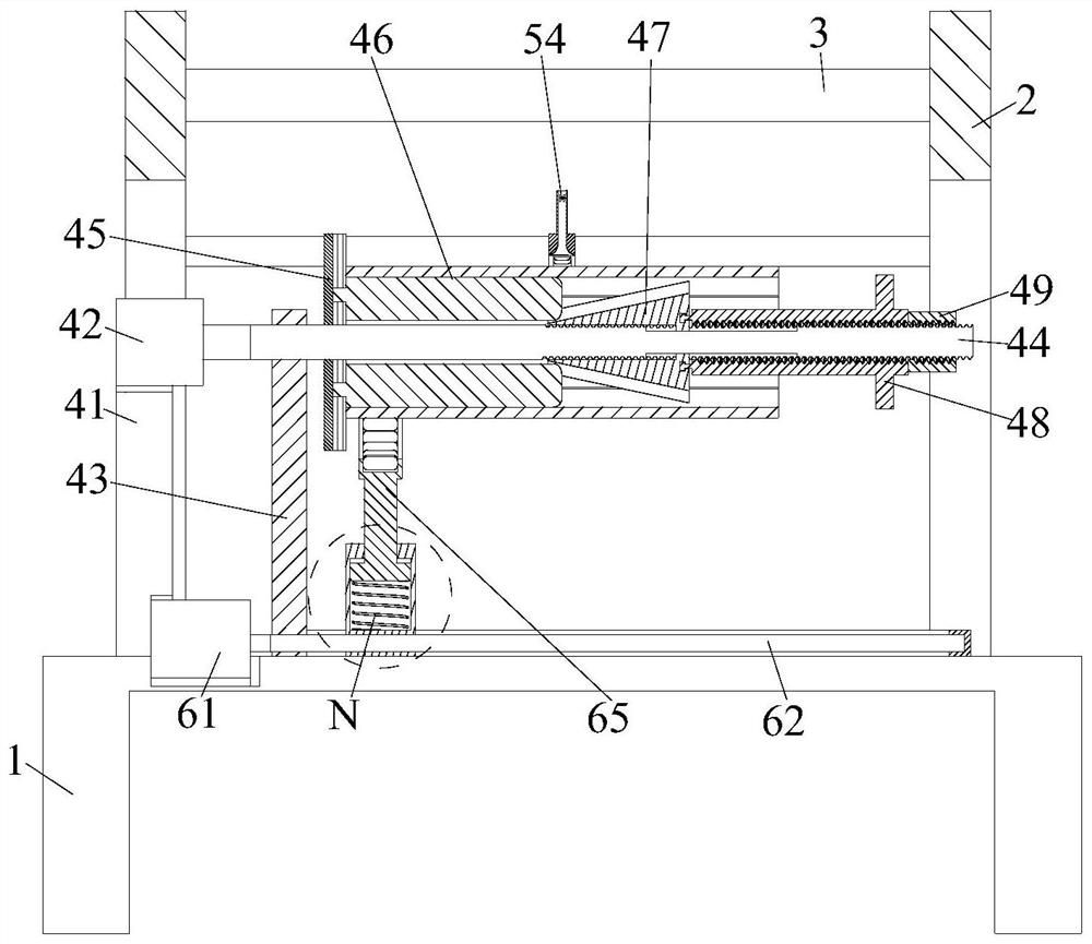
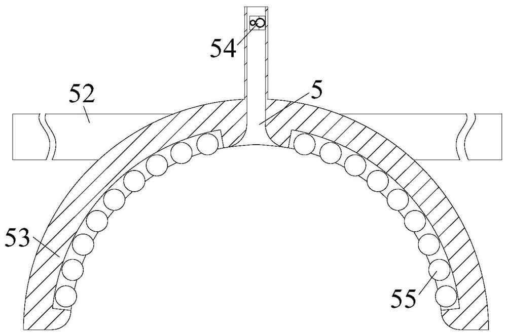
[0036] A transformer manufacturing process coil making and winding machine, including a mounting table 1, two U-shaped side plates 2, a fixed rod 3, a supporting rotating device 4, a winding device 5 and a rolling device 6, and the upper end of the mounting table 1 is left and right U-shaped side plates 2 are welded symmetrically on both sides, and the upper end of the U-shaped side plate 2 is installed with a fixed rod 3 through a sliding fit. There is a winding device 5, and the end of the winding device 5 is provided with a rolling device 6, and the rolling device 6 is arranged in the middle of the upper end of the installation platform 1; wherein:

[0037] The supporting and rotating device 4 includes a mounting column 41, a rotating motor 42,...


PUM


Abstract

The invention relates to a winding machine for manufacturing coils in the transformer manufacturing process, which includes a mounting table, two U-shaped side plates, a fixed rod, a supporting rotating device, a winding device and a rolling device, and the left and right sides of the upper end of the mounting table are welded symmetrically. There is a U-shaped side plate, the upper end of the U-shaped side plate is installed with a fixed rod through sliding fit, the middle part of the installation platform is equipped with a supporting rotating device, a winding device is installed between the supporting rotating device and the fixed rod, and the end of the winding device is provided with a Rolling device, the rolling device is arranged in the middle part of the upper end of the installation platform. The invention provides a winding machine for winding coils in the manufacturing process of transformers, which can solve the problem that when the existing equipment is wound, the transformer skeleton is easily deformed or even broken due to the large number of winding turns, and the winding of the coils is easy to occur during the coil winding process. The phenomenon of crossing, knotting and sinking of wires, and problems such as scratches or even breaking of enameled wires when existing equipment is wound.

Description

technical field [0001] The invention relates to the technical field of transformer manufacturing, in particular to a coil manufacturing and winding machine in the transformer manufacturing process. Background technique [0002] Transformer is a device that uses the principle of electromagnetic induction to change AC voltage. The main components are primary coil, secondary coil and iron core (magnetic core). The main functions of the transformer are: voltage transformation, current transformation, impedance transformation, isolation, voltage stabilization (magnetic saturation transformer), etc. In the process of making a transformer, the winding of the coil is particularly important. In the process of coil winding, the wires are wound one by one, and the wires are insulated from each other. [0003] In actual production and manufacturing, the existing transformer manufacturing equipment often has the following problems in the actual operation of winding: [0004] (1) When t...

Claims


Application Information

Patent Timeline
Patent Type & Authority Patents(China)
IPC IPC(8): H01F41/06H01F41/082
CPCH01F41/06H01F41/082
Inventor 胡梦婷张雨
Owner 威海众成电子有限公司
Learn More