Double-connected linkage switch device and electrical equipment

A linkage switch and linkage rod technology, applied in the field of electrical equipment and switch elements, can solve the problems of large switch line loss and voltage drop, occupying a large design space, etc., to achieve reduced line loss and voltage drop, small volume and space, Energy Saving Effect

Pending Publication Date: 2020-01-10
吴光
View PDF0 Cites 0 Cited by
  • Summary
  • Abstract
  • Description
  • Claims
  • Application Information

AI Technical Summary

Problems solved by technology

For this reason, the present invention proposes a double-connected linkage switch device and electrical equipment, which can overcome the defects of large switch line loss and voltage drop, and occupying a large design space

Method used


Image

  • Double-connected linkage switch device and electrical equipment
  • Double-connected linkage switch device and electrical equipment
  • Double-connected linkage switch device and electrical equipment

Examples


no. 1 example

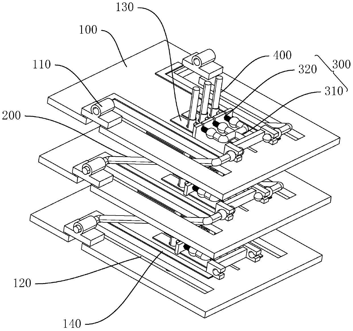
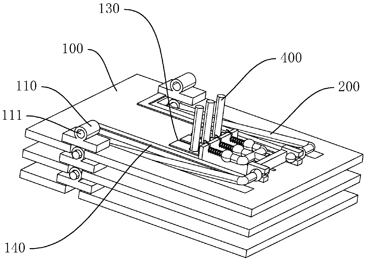
[0039] figure 1 For a structural diagram of an embodiment of a dual linkage switch device, refer to figure 1 The dual linkage switch device in this embodiment includes a circuit board 100, a connection terminal 110, a moving assembly 300, a linkage rod 200, and a power shaft 400. There are no less than two circuit boards 100, and the circuit boards 100 are stacked and arranged. In this embodiment, there are three circuit boards 100. The number of circuit boards 100 can be flexibly changed according to actual usage requirements; the connecting terminals 110 are fixed On the circuit board 100 and electrically connected to the circuit board 100, the connecting terminal 110 is used to connect with the linkage rod 200 to realize the connection of the linkage rod 200 between adjacent circuit boards 100; the circuit board 100 is provided with a moving channel 120 , For the linkage rod 200 to pass through, so that the linkage rod 200 extends to the adjacent circuit board 100; the moving...

no. 2 example

[0050] The dual linkage switch device in the first embodiment is provided with three power shafts 400, three first leads 130, and three electrodes 320 to achieve "multiple throw". By providing multiple electrodes 320, multiple paths of the same or different Power supply, with high application flexibility.

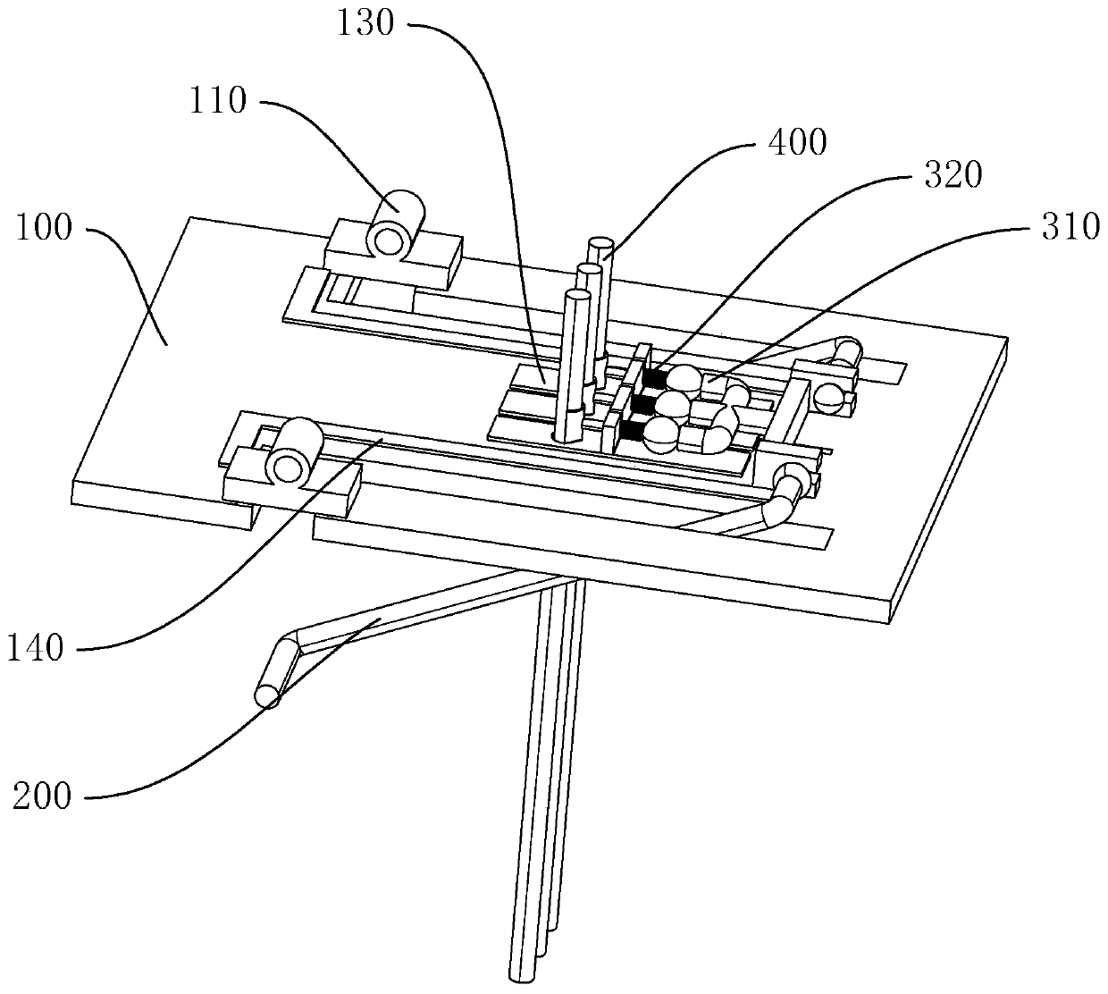
[0051] Reference Picture 10 The difference between this embodiment and the second embodiment is that two electrodes 320 are provided in this embodiment. The electrodes 320 are arranged on both sides of the pushing member 310. When the electrodes 320 are connected to the power shaft 400, a "double throw ".

no. 3 example

[0053] Reference Picture 11 The difference between this embodiment and the first embodiment is that an electrode 320 is provided in this embodiment. The electrode 320 is arranged at the center of the pushing member 310. When the electrode 320 is connected to the power shaft 400, a "single throw" is realized. .

[0054] It needs instructions that more than three electrodes 320 can be provided, which can be selected reasonably according to different usage requirements.

[0055] The dual linkage switch in the present invention can realize circuit on and off during the folding process of the circuit board 100, and can be applied to mechatronics equipment, such as shop windows, curtain walls, stage backgrounds, media terminals, vehicle screens and other fields. The present invention also provides an electrical equipment including the above-mentioned double linkage switch device, and the electrical equipment is applicable to any mechatronics equipment in the above-mentioned field.


PUM


Abstract

The invention discloses a double-connected linkage switch device and electrical equipment. The double-connected linkage switch device comprises circuit boards, a connecting terminal, a moving assembly, a linkage rod and a power shaft. The circuit boards are stacked. A first lead and a second lead are arranged on each circuit board. A movable channel is arranged on each circuit board. One end of the linkage rod is rotatably connected with a push member, and the other end of the linkage rod penetrates through the movable channel to be rotatably connected with the connecting terminal on the adjacent circuit board. The linkage rod can rotate based on the connecting terminal so as to enable the linkage rod to contact or be away from the second lead. The push member can move by following the rotation of the linkage rod and push the electrode to be crimped or away from the power shaft so as to enable the power shaft to connect or be away from the first lead. The switch device takes electricity in a parallel manner so as to reduce line loss and voltage drop caused by printing current convergence and save energy; in addition, the circuit boards are stacked so as to reduce the volume and occupied space of the switch and adapt to the design of different application scene and facilitate product design and development.

Description

Technical field [0001] The present invention relates to the technical field of electrical equipment and switching elements, in particular to a double linkage switch and electrical equipment. Background technique [0002] A switch refers to an electronic component that can open a circuit, interrupt current, or conduct other circuits, and can turn on and off the circuit, and has been widely used in electrical equipment in various fields. The traditional conduction between different components is connected in series through the PCB, resulting in a large current flowing in the circuit, which can easily cause increased line loss and voltage drop, and occupy a large PCB board design space, which increases the product Design difficulty is not conducive to product design and development. Summary of the invention [0003] The present invention aims to solve at least one of the technical problems existing in the prior art. To this end, the present invention proposes a dual linkage switch ...

Claims


Application Information

Patent Timeline
IPC IPC(8): H01H3/32
CPCH01H3/32
Inventor 吴光
Owner 吴光
Why Eureka
Try Eureka