Agricultural watering mechanical device for irrigation

A mechanical equipment and agricultural technology, applied in the field of irrigation equipment, can solve the problems of poor flexibility and small glue range, and achieve the effects of simple structure, increased spraying range and convenient use.

Active Publication Date: 2020-01-14
佳木斯市潜兴农业机械研发有限公司
View PDF8 Cites 4 Cited by
  • Summary
  • Abstract
  • Description
  • Claims
  • Application Information

AI Technical Summary

Problems solved by technology

[0004] The purpose of the present invention is to solve the shortcomings of the fixed position of agricultural watering machinery and equipment in the prior ar...

Method used


Image

  • Agricultural watering mechanical device for irrigation
  • Agricultural watering mechanical device for irrigation
  • Agricultural watering mechanical device for irrigation

Examples


Embodiment 1

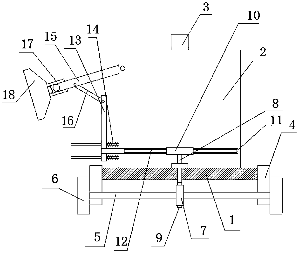
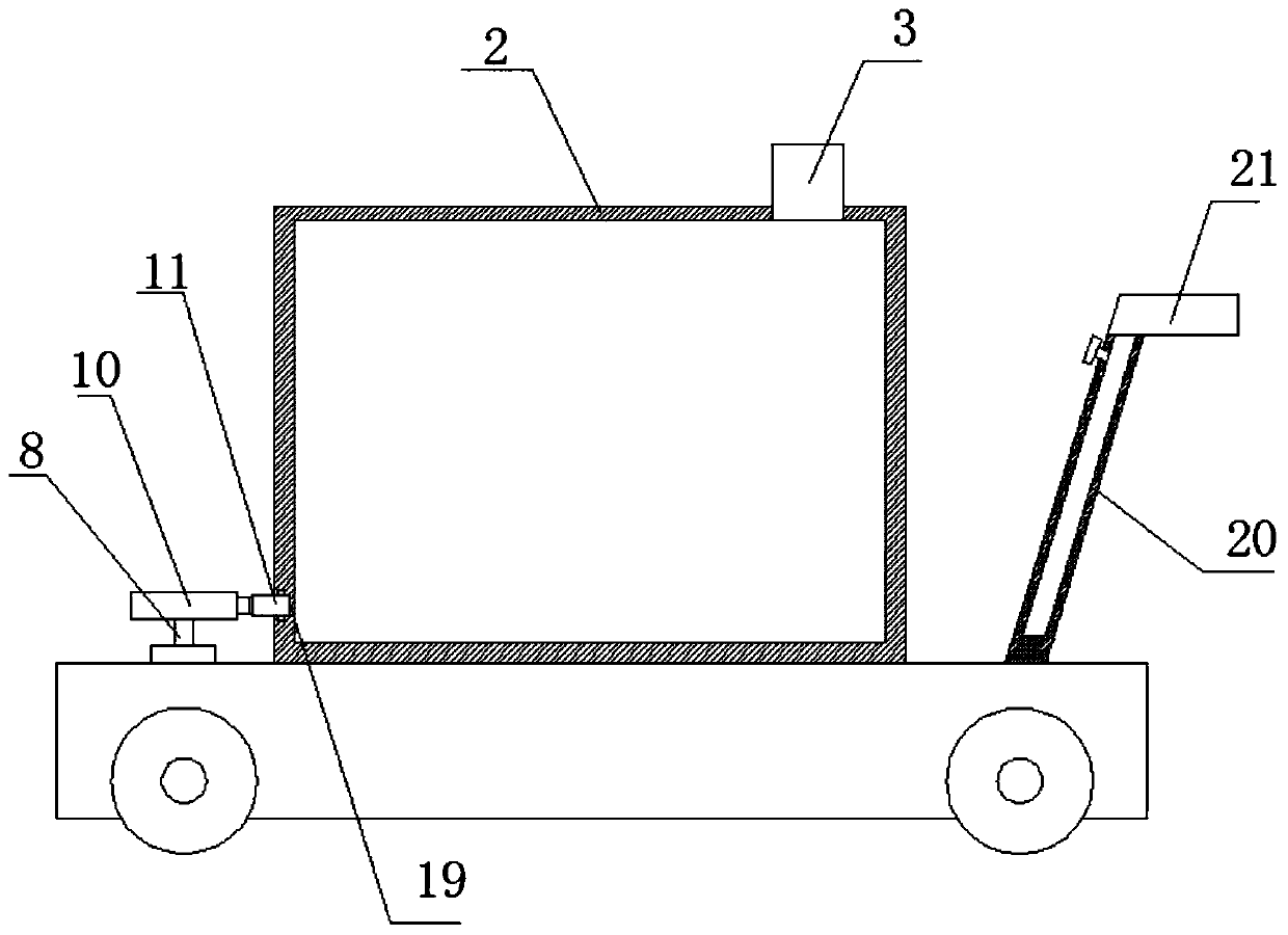
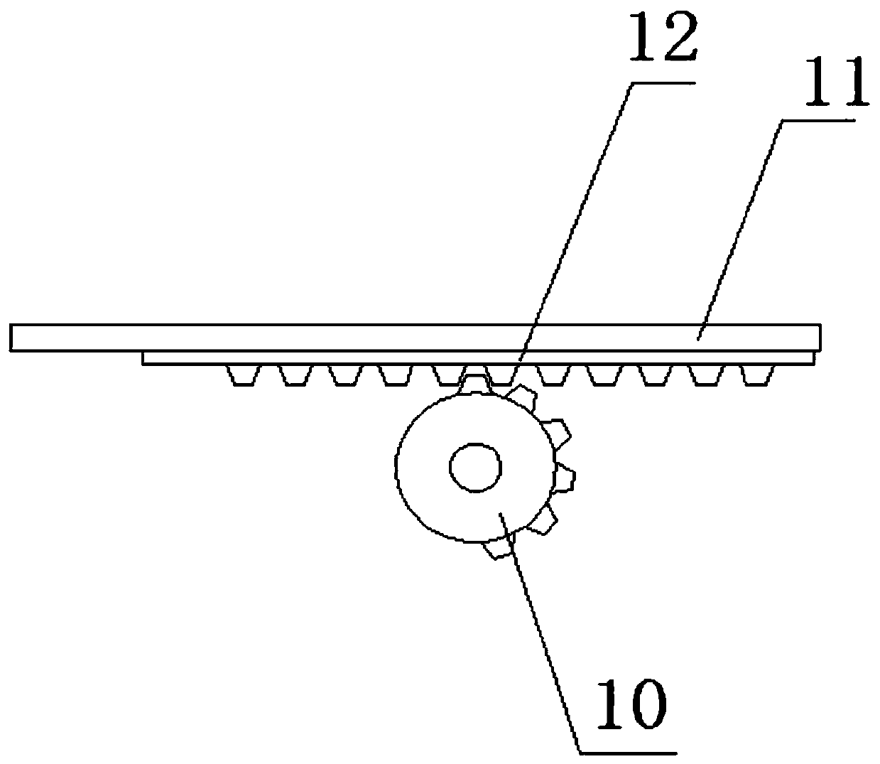
[0029] refer to Figure 1-6 , a kind of agricultural watering mechanical equipment for irrigation, comprising a mounting base 1, support plates 4 are fixedly installed on both sides of the mounting base 1, two rotating shafts 5 are mounted on the two supporting plates 4, and the two rotating shafts Both ends of 5 are fixedly equipped with rollers 6, the top of the installation base 1 is fixedly installed with a water tank 2, the top of the water tank 2 is provided with a water injection port 3, and the installation base 1 is provided with a rotation hole, and a vertical rod 8 is installed in the rotation hole , the bottom end of the vertical rod 8 extends to the bottom of the installation base 1 and is fixedly installed with a worm 9, and the outer fixed sleeve of one of the two rotating shafts 5 is provided with a worm wheel 7, the worm wheel 7 meshes with the worm 9, and the vertical The top of the rod 8 extends to the top of the installation base 1 and is fixedly installed ...

Embodiment 2

[0040] refer to Figure 1-6 , a kind of agricultural watering mechanical equipment for irrigation, comprising a mounting base 1, both sides of the mounting base 1 are fixed with support plates 4 by bolts, and two rotating shafts 5 are installed on the two support plates 4, two Both ends of the rotating shaft 5 are fixed with rollers 6 by bolts, the top of the installation base 1 is fixed with a water tank 2 by bolts, the top of the water tank 2 is provided with a water injection port 3, and the installation base 1 is provided with a rotation hole. A vertical rod 8 is installed for rotation, and the bottom end of the vertical rod 8 extends to the bottom of the installation base 1 and is fixed with a worm 9 by bolts. The outer fixed sleeve of one of the two rotating shafts 5 is provided with a worm gear 7, and the worm gear 7 is meshed with the worm 9, the top of the vertical rod 8 extends to the top of the installation base 1 and is fixed with a sector gear 10 by bolts, a groov...


PUM


Abstract

The invention belongs to the field of irrigation devices, particularly discloses an agricultural watering mechanical device for irrigation, and aims to solve the problems that a position of an existing agricultural watering mechanical device is fixed, the watering range of the device is small, and use flexibility is poor. The technical scheme includes that the device comprises a mounting base, supporting plates are fixedly mounted on two sides of the mounting base, two rotating shafts are rotatably mounted on the two supporting plates, rollers are fixedly mounted at two ends of the rotating shafts, a water tank is fixedly mounted at the top of the mounting base, a water filling port is formed in the top of the water tank, a rotating hole is formed in the mounting base, a vertical rod is rotatably mounted in the rotating hole, the bottom end of the vertical rod extends below the mounting base, and a worm is fixedly mounted at the bottom end of the vertical rod. According to the device,the spraying range of a sprayer is widened, watering efficiency can be improved, an angle of the sprayer can be adjusted, and the heights of two handles can be adjusted, so that the device adapts to use of different heights of people and is simple in structure and convenient to use.

Description

technical field [0001] The invention relates to the technical field of irrigation equipment, in particular to agricultural watering mechanical equipment for irrigation. Background technique [0002] Irrigation, that is, watering the land, the principle of irrigation is that the amount of irrigation, the frequency and time of irrigation should be determined according to the water demand characteristics of medicinal plants, growth stage, climate, and soil conditions, and it should be timely, appropriate, and rational irrigation. The types mainly include pre-sowing irrigation, seedling irrigation, growth period irrigation and winter irrigation. [0003] The existing agricultural watering machinery and equipment are fixed in position, the range of glue is small, and the flexibility of use is poor. Therefore, we propose an agricultural watering machinery and equipment for irrigation to solve the above problems. Contents of the invention [0004] The purpose of the present inve...

Claims


Application Information

Patent Timeline
IPC IPC(8): A01G25/09
CPCA01G25/09
Inventor 不公告发明人
Owner 佳木斯市潜兴农业机械研发有限公司
Why Eureka
Try Eureka