Calibration tool for ophthalmology optical imaging and biological parameter measuring instrument and using method of calibration tool

A technology of optical imaging and biological parameters, applied in medical science, application, equipment for testing eyes, etc., can solve problems such as inability to detect or calibrate

Active Publication Date: 2020-01-14
NAT INST OF METROLOGY CHINA
View PDF8 Cites 4 Cited by
  • Summary
  • Abstract
  • Description
  • Claims
  • Application Information

AI Technical Summary

Problems solved by technology

[0006] In order to solve the problem that the existing single calibration tool cannot detect or calibrate parameters such as field angle, resolution, depth measurement, eye axis length and signal-to-noise ratio of ophthalmic imaging equipment and ophthalmic biological parameter measuring instrument, the present invention discloses a A calibration tool for ophthalmic optical imaging and biological parameter measuring instruments and its application method. Its detection range covers parameters such as field of view, lateral resolution, axial resolution, depth measurement, eye axial length, and signal-to-noise ratio. , can be used for detection and calibration of ophthalmic optical imaging and biological parameter measuring instruments

Method used


Image

  • Calibration tool for ophthalmology optical imaging and biological parameter measuring instrument and using method of calibration tool
  • Calibration tool for ophthalmology optical imaging and biological parameter measuring instrument and using method of calibration tool
  • Calibration tool for ophthalmology optical imaging and biological parameter measuring instrument and using method of calibration tool

Examples


Embodiment Construction

[0043] The implementation of the present invention will be described in detail below with reference to the accompanying drawings and embodiments, so as to fully understand how the present invention applies technical means to solve technical problems and achieve the realization process of technical effects and implement them accordingly. It should be noted that, as long as there is no conflict, each embodiment of the present invention and each feature in each embodiment can be combined with each other, and the technical solutions formed are all within the protection scope of the present invention.

[0044] Meanwhile, in the following description, many specific details are set forth for the purpose of explanation to provide a thorough understanding of the embodiments of the present invention. However, it is obvious to those skilled in the art that the present invention can be implemented without the specific details or the specific manner described herein.

[0045] As mentioned above...


PUM


Abstract

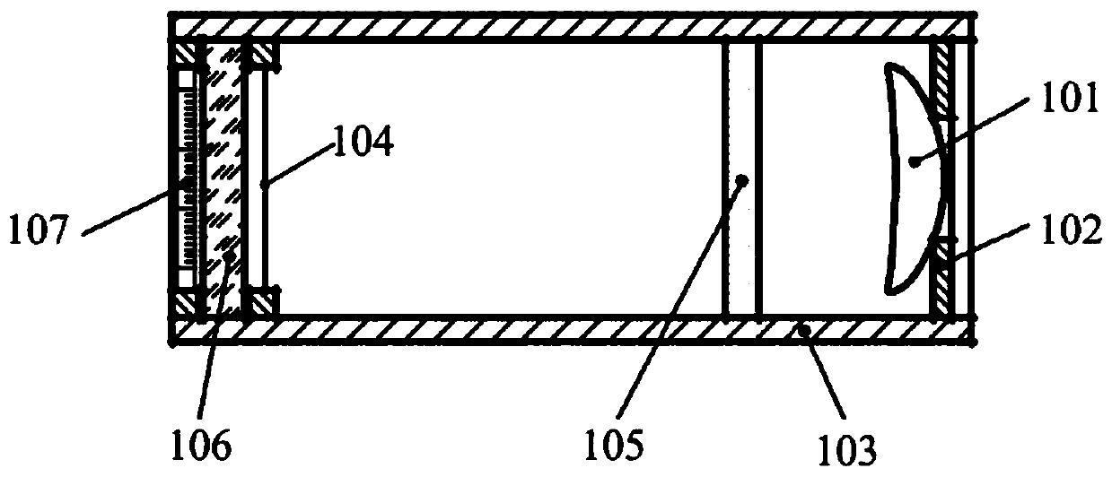
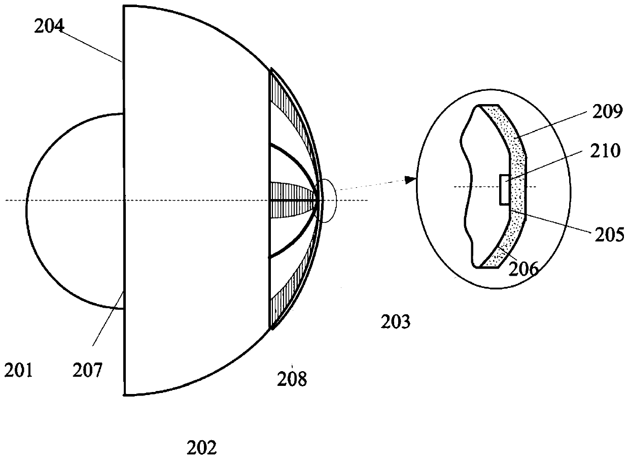
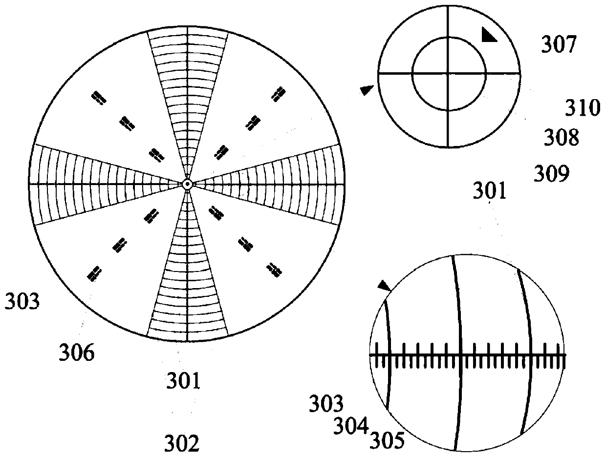
The invention relates to a calibration tool for an ophthalmology optical imaging and biological parameter measuring instrument and a using method of the calibration tool. The calibration tool comprises a first lens, a second lens and a PDMS mold body, wherein the first lens comprises a first curve and a first plane; the second lens comprises a second curve, a second plane and a third plane, and the second plane and the third plane are parallel; resolution ratio testing microspheres which are uniformly distributed are in the PDMS mold body; the first plane is attached to the second plane; the PDMS mold body is attached to the third plane and a part of the second curve; an empty chamber is formed between the third plane and the PDMS mold body; the first lens, the second lens, the PDMS mold body and the empty chamber are symmetric about the same axis; the curvature radius of the first lens is smaller than that of the second lens; a visual field angle scale and a resolution ratio line aligning pattern are arranged between the second curve and the PDMS mold body; and an image calibration line is arranged on the third plane.

Description

Technical field [0001] This application relates to the technical field of instrument detection, and in particular to a calibration tool for ophthalmic optical imaging and biological parameter measuring instruments and a method of use thereof. Background technique [0002] Fundus optical imaging obtains human eye structure information through two-dimensional or three-dimensional imaging technology, and is widely used in clinical diagnosis with its advantages of non-invasive and high precision. Fundus imaging diagnostic equipment mainly includes posterior segment optical coherence tomography scanners, fundus cameras, etc., as well as optical coherence tomography scanners with fundus photography functions, ophthalmic optical biometers and other equipment. The maximum measurable field of view of the fundus imaging medical equipment affects the imaging range, and the resolution determines the smallest resolvable structure size. They are important parameters that characterize the measu...

Claims


Application Information

Patent Timeline
Patent Type & Authority Applications(China)
IPC IPC(8): A61B3/14A61B3/10
CPCA61B3/0016A61B3/1005A61B3/102A61B3/14
Inventor 王红婷刘文丽胡志雄李飞李修宇洪宝玉李姣
Owner NAT INST OF METROLOGY CHINA
Why Eureka
Try Eureka