
Split type self-speed-change reciprocating linear motor firing gear

A technology of reciprocating straight line and firing device, which is applied to electromechanical devices, firing/trigger mechanisms, electrical components, etc., can solve problems such as non-compliance with firearms storage and storage regulations, inaccurate firing action, and increasing the volume of electromagnets. Simple application, low production cost, high thrust effect

Pending Publication Date: 2020-01-14
中国人民解放军陆军炮兵防空兵学院士官学校
View PDF0 Cites 0 Cited by
  • Summary
  • Abstract
  • Description
  • Claims
  • Application Information

AI Technical Summary

Problems solved by technology

[0003] Each firing action of the traditional firing mechanism is indeed reliable, but there are many restrictions: First, the use of AC electromagnets requires an AC power supply environment. If the DC electromagnet wants to meet the pulling force required by the trigger firing, either increase the power supply voltage or increase the volume of the electromagnet
The second is that the traditional firing mechanism generally needs to be fixed with the automatic rifle and the gun frame. After shooting, the gun cannot be removed from the gun frame, which does not meet the requirements for the storage and storage of firearms.
[0004] If the firing mechanism adopts an integrated reciprocating linear motor on the market, not only the above-mentioned problems exist in the installation method, but also if the reciprocating speed is "fast", the push and pull force is insufficient to make the firing action unreliable, and if the reciprocating speed is "slow", the firing mechanism cannot be timely. Get rid of the restriction on the trigger, when the trigger is in the ready state, the backseat of the gun frame re-entry mechanism is reset and the firing vibration often occurs

Method used


Image

  • Split type self-speed-change reciprocating linear motor firing gear
  • Split type self-speed-change reciprocating linear motor firing gear
  • Split type self-speed-change reciprocating linear motor firing gear

Examples


Embodiment Construction

[0035] In order to make the object, technical solution and advantages of the present invention clearer, the present invention will be described in detail below in conjunction with the accompanying drawings and specific embodiments.

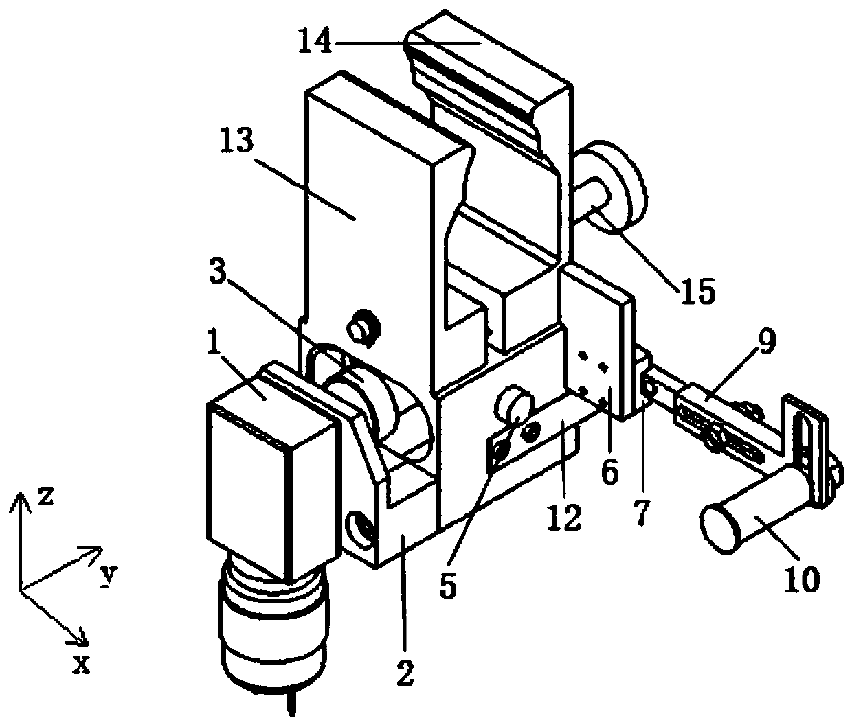
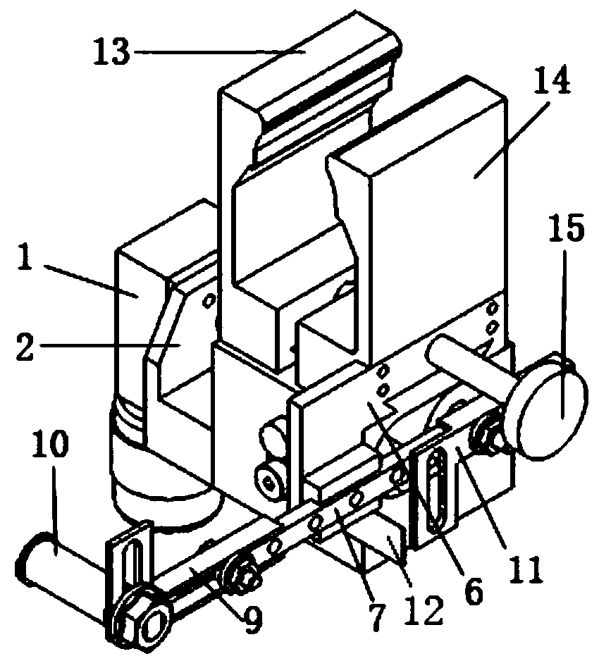
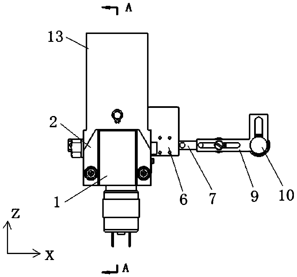
[0036] Such as Figure 1-3 As shown, a discrete self-variable speed reciprocating linear motor firing device provided by the present invention includes a power source mechanism, a gun clamp, a toggle slider 4, a reciprocating linear push-pull mechanism and a reset mechanism, wherein the power source mechanism and the reciprocating linear The push-pull mechanism is respectively arranged on both sides of the gun clamp, and the reciprocating linear push-pull mechanism can slide along the X-axis direction, and the X-axis direction is the firing direction. The toggle slider 4 can be slidably arranged under the gun clamp along the X-axis direction, and the two ends of the toggle slider 4 are respectively connected with the output end of the power source...


PUM


Abstract

The invention relates to an electric firing gear, in particular to a split type self-speed-change reciprocating linear motor firing gear. The split type self-speed-change reciprocating linear motor firing gear comprises a power source mechanism, a gun clamping clamp, a thumbing sliding block, a reciprocating linear push-and-pull mechanism and a reset mechanism. The power source mechanism and the reciprocating linear push-and-pull mechanism are arranged on the two sides of the gun clamping clamp separately, the reciprocating linear push-and-pull mechanism can slide in the X-axis direction, thethumbing sliding block can be slidingly arranged below the gun clamping clamp in the X-axis direction, the two ends of the thumbing sliding block are connected with the output end of the power sourcemechanism and the reciprocating linear push-and-pull mechanism separately, the thumbing sliding block is used for transmitting power of the power source mechanism to the reciprocating linear push-and-pull mechanism, and the reset mechanism is arranged between the gun clamping clamp and the reciprocating linear push-and-pull mechanism. The split type self-speed-change reciprocating linear motor firing gear is fixed to a rapid clamping clamp of a gun rack along with an automatic rifle, a firing rod is transversely moved to the pre-firing position in a trigger protective ring, limitation on a trigger can be released in time after firing is completed, the trigger is naturally reset, and the operation is convenient and reliable.

Description

technical field [0001] The invention relates to an electric percussion mechanism, in particular to a discrete self-variable speed reciprocating linear motor percussion device. Background technique [0002] During the firing process of automatic weapon products, electric firing mechanisms are usually used. Most of the electric firing mechanisms currently used are push-pull structures of AC electromagnets or DC electromagnets, that is, a firing hook is fixed before the trigger of an automatic rifle, and after the electromagnet is energized, the electromagnet attracts and pulls the firing hook to drive the trigger to realize the firing action. [0003] The firing action of the traditional firing mechanism is indeed reliable, but there are many restrictions: First, the use of AC electromagnets requires an AC power supply environment. If the DC electromagnet wants to meet the pulling force required for firing the trigger, either increase the power supply voltage or increase the ...

Claims


Application Information

Patent Timeline
IPC IPC(8): F41A19/59H02K7/06
CPCF41A19/59H02K7/06
Inventor 李魁峰郭立威孙跃辉谭越郡衣锦辉王权刘洋吕泉中顾闻范景韬杨劲松曹士信王章龙祁晓宇高克斌高岩李帅冯旋
Owner 中国人民解放军陆军炮兵防空兵学院士官学校
Learn More