Probe head with linear probe

一种探针头、探针的技术,应用在探针卡部件领域,能够解决不适用等问题

Active Publication Date: 2020-01-14
MPI CORP
View PDF11 Cites 1 Cited by
  • Summary
  • Abstract
  • Description
  • Claims
  • Application Information

AI Technical Summary

Problems solved by technology

However, most of the existing probes with stoppers add protruding stoppers to the outer peripheral surface of the original probe. This method is not suitable for wires made by cutting round metal wires. probe

Method used


Image

  • Probe head with linear probe
  • Probe head with linear probe
  • Probe head with linear probe

Examples


Embodiment Construction

[0053] First of all, it is explained here that in the embodiments and drawings to be described below, the same reference numerals denote the same or similar components or structural features. The detailed structure, features, assembly or usage of the probe head with linear probes provided by the present invention will be described in the detailed description of the implementation. However, those skilled in the field of the present invention should understand that these detailed descriptions and examples are specific examples of the present invention, and are only used to illustrate the present invention, not to limit the protection scope of the present invention. The present invention will be described in detail below in conjunction with the accompanying drawings and embodiments.

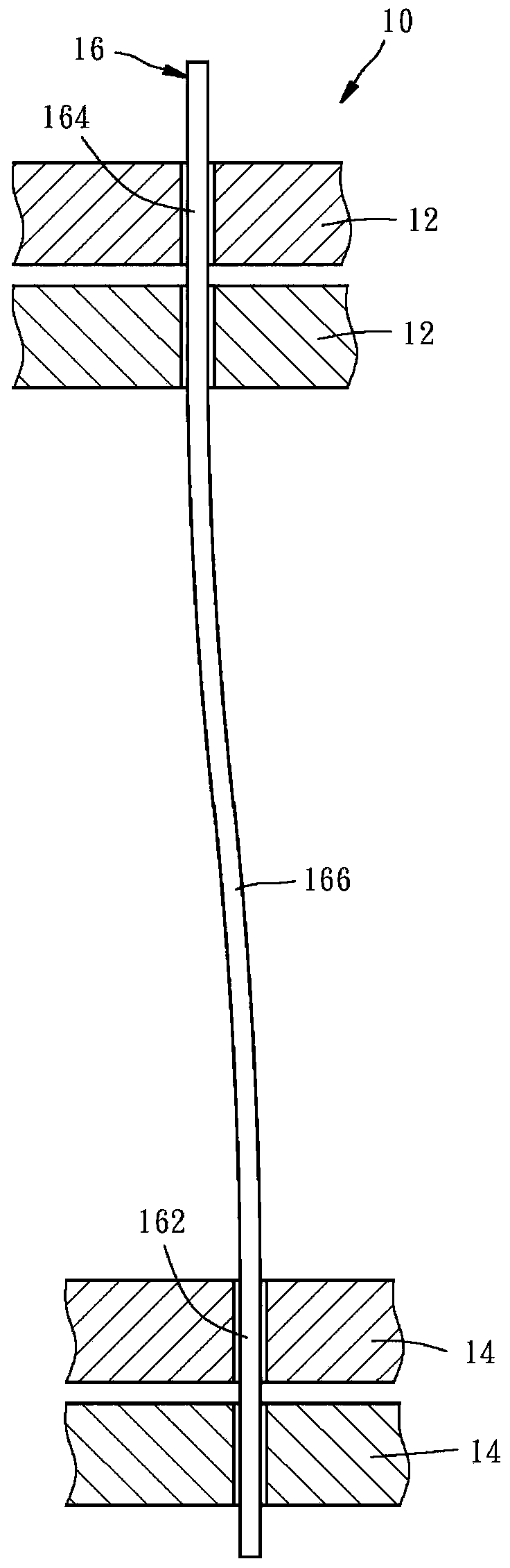
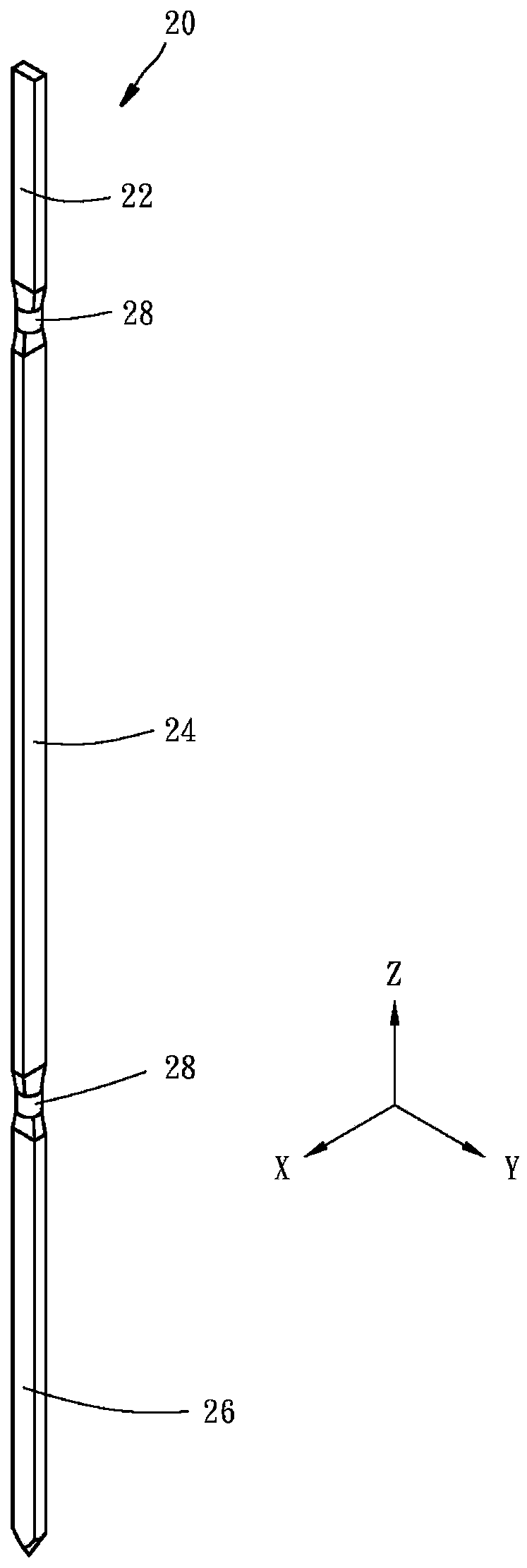
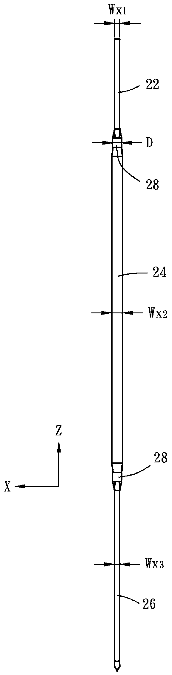
[0054] like Figure 2 to Figure 4 As shown, the linear probe 20 provided by the first preferred embodiment of the present invention is composed of a cylindrical needle body (such as figure 1 The s...


PUM


Abstract

The invention relates to a probe head with a linear probe. The probe head has a linear probe, and upper and lower guide plate units having upper and lower installation holes respectively, at least oneof the tail portion, the body portion and the head portion of the linear probe being flattened and thereby defined with a first width axis and a second width axis, each of the tail portion, the bodyportion and the head portion being defined with a first width along the first width axis and a second width along the second width axis, the first width and the second width of the body portion beingrespectively larger than and smaller than the first width and the second width of at least one of the tail portion and the head portion, the tail and head portions being inserted into upper and lowerinstallation holes respectively which are offset from each other along the second width axis so that the body portion is curved. As a result, the probes of the same probe head are consistent in bending direction and moving behavior and prevented from rotation, drop and escape.

Description

technical field [0001] The present invention relates to a probe card part, in particular to a probe head with a linear probe. Background technique [0002] like figure 1 As shown, the probe head 10 of the existing linear probe mainly includes at least two upper guide plates 12, at least two lower guide plates 14, and a plurality of probes 16 (for simplified drawings, figure 1 Only one probe 16 is drawn in the figure), the needles 162 of each probe 16 (i.e., a linear probe) are used to touch the conductive contact of an object under test (not shown in the figure), and the needles 162 are installed on the lower guide plate 14 Above, the needle tail 164 of each probe 16 is used to abut against a conductive contact of a circuit board or a space transformer (not shown in the figure), and the needle tail 164 passes through the upper guide plate 12 . In the process of assembling the probe head 10, after these probes 16 are passed on these guide plates 12, 14, the upper guide plat...

Claims


Application Information

Patent Timeline
Patent Type & Authority Applications(China)
IPC IPC(8): G01R1/067G01R1/073
CPCG01R1/073G01R1/067G01R1/06716G01R1/06733G01R1/0675G01R1/07307G01R1/07357
Inventor 陈子扬韦嘉茹
Owner MPI CORP
Why Eureka
Try Eureka