Driving circuit and driving method thereof, micro-fluidic substrate and micro-fluidic device

A driving circuit and capacitor technology, applied in the field of microfluidics, can solve the problem that the driving voltage is not enough to drive the droplet to move

Pending Publication Date: 2020-01-14
SHANGHAI TIANMA MICRO ELECTRONICS CO LTD
View PDF5 Cites 6 Cited by
  • Summary
  • Abstract
  • Description
  • Claims
  • Application Information

AI Technical Summary

Problems solved by technology

[0005] Embodiments of the present invention provide a driving circuit and its driving method, a microfluidic substrate and a microfluidic device to solve the technical problem in the prior art that the driving voltage provided by the active driving chip is not enough to drive the droplet movement

Method used


Image

  • Driving circuit and driving method thereof, micro-fluidic substrate and micro-fluidic device
  • Driving circuit and driving method thereof, micro-fluidic substrate and micro-fluidic device
  • Driving circuit and driving method thereof, micro-fluidic substrate and micro-fluidic device

Examples


Embodiment Construction

[0043] The present invention will be further described in detail below in conjunction with the accompanying drawings and embodiments. It should be understood that the specific embodiments described here are only used to explain the present invention, but not to limit the present invention. In addition, it should be noted that, for the convenience of description, only some structures related to the present invention are shown in the drawings but not all structures.

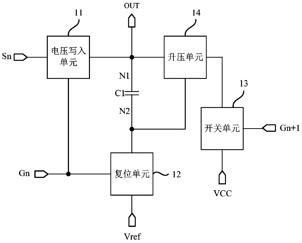
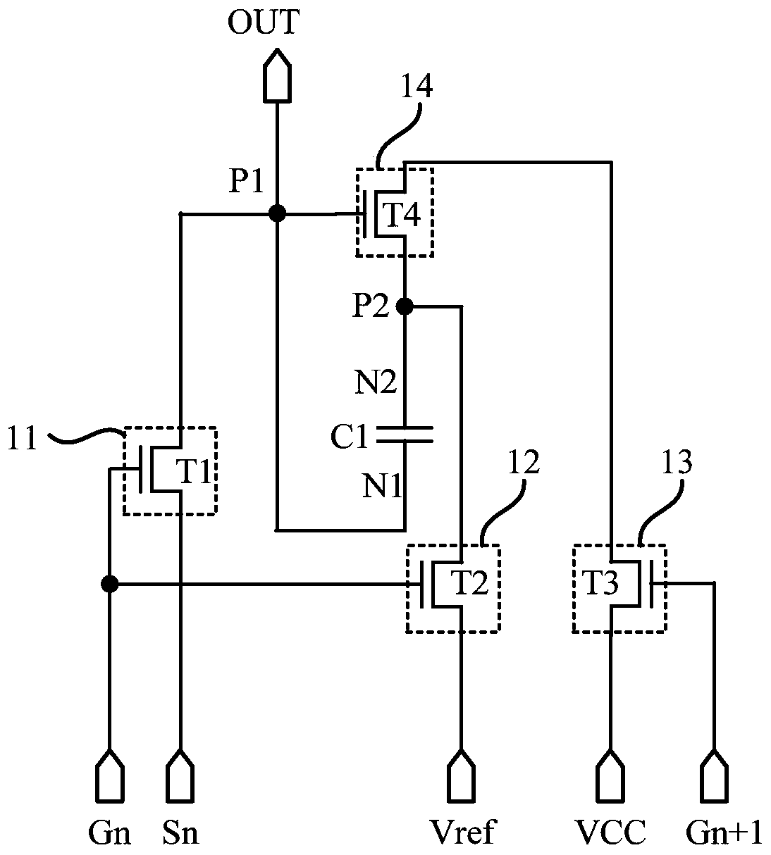
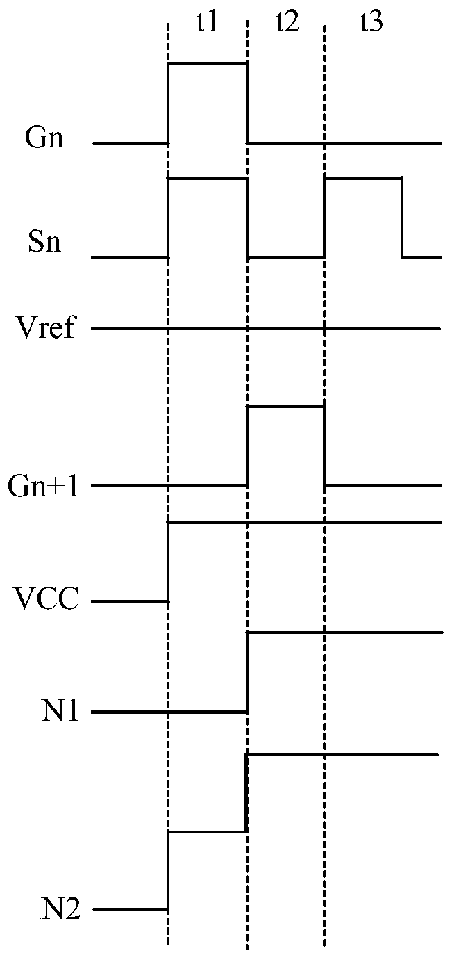
[0044] figure 1 It is a structural schematic diagram of a driving circuit provided by an embodiment of the present invention. Such as figure 1 As shown, the drive circuit includes a voltage writing unit 11, a boost unit 14, a reset unit 12, a switch unit 13, and a first capacitor C1. The drive circuit also includes a first scanning signal terminal Gn for transmitting signals, a second scanning The signal terminal Gn+1, the first voltage signal terminal Sn, the second voltage signal terminal VCC, the reset signal...


PUM


Abstract

Embodiments of the invention disclose a driving circuit and a driving method thereof, a micro-fluidic substrate and a micro-fluidic device. The driving circuit is characterized in that: a first voltage signal of a first voltage signal end is transmitted to a first end of a first capacitor through a voltage write-in unit, and a reset signal of a reset signal end is transmitted to a second end of the first capacitor through a reset unit, so that a voltage difference is generated between the first end of the first capacitor and the second end of the first capacitor; then a second voltage signal of a second voltage signal end is transmitted to the second end of the first capacitor by a switching unit through a boosting unit; in this way, when a high potential signal needs to be output, as a potential signal of the second end of the first capacitor is increased, a potential signal of the first end of the first capacitor is higher than a potential signal of the first voltage signal of the first voltage signal end.

Description

technical field [0001] The invention relates to the field of microfluidic technology, in particular to a driving circuit and a driving method thereof, a microfluidic substrate and a microfluidic device. Background technique [0002] Microfluidics is a technology for precisely controlling and manipulating microscale fluids, which has great application prospects in the fields of biology, chemistry, and medicine. Among them, the microfluidic device is the main platform for the realization of microfluidic technology. [0003] A microfluidic device usually includes a control circuit and a driving electrode. The control circuit is used to provide voltage to the driving electrode, so that an electric field is formed between adjacent driving electrodes, and the droplet moves under the driving action of the electric field. The control circuit can adopt a passive driver chip or an active driver chip. Among them, the driving capability of the passive driving chip is limited. When it ...

Claims


Application Information

Patent Timeline
Patent Type & Authority Applications(China)
IPC IPC(8): G05F1/56B01L3/00
CPCB01L3/5027B01L2200/14G05F1/561
Inventor 周一安林柏全秦锋李小和席克瑞
Owner SHANGHAI TIANMA MICRO ELECTRONICS CO LTD
Why Eureka
Try Eureka