Reactive power compensation device

A compensation device, compensation capacitor technology, applied in reactive power compensation, reactive power adjustment/elimination/compensation, circuit devices, etc., can solve the problems of a large number of idle, weak high-frequency harmonic absorption capacity, large harmonic overload, etc. , to achieve the effect of not easily overloaded and damaged

Pending Publication Date: 2020-01-14
韶关市佰瑞节能科技有限公司
View PDF0 Cites 1 Cited by
  • Summary
  • Abstract
  • Description
  • Claims
  • Application Information

AI Technical Summary

Problems solved by technology

[0006] However, in the face of the trend of automation and intelligence of the loads connected to the distribution network, the harmonic spectrum injected into the distribution network is complex and changeable. The above-mentioned existing reactive power compensation devices have the following defects: First, the existing reactive power The tuned filter composed of series reactor L and capacitor C in the compensation device can only filter out a specific one or two adjacent harmonics in the distribution network, with limited filtering ability and weak ability to absorb high-frequency harmonics; Second, in the face of the distribution network harmonics with complex spectrum, the existing reactive power compensation device itself has a greater risk of harmonic overload damage
The above defects make the existing reactive power compensation devices unable to meet the needs of users and are left idle in large quantities

Method used


Image

  • Reactive power compensation device
  • Reactive power compensation device
  • Reactive power compensation device

Examples


Embodiment 1

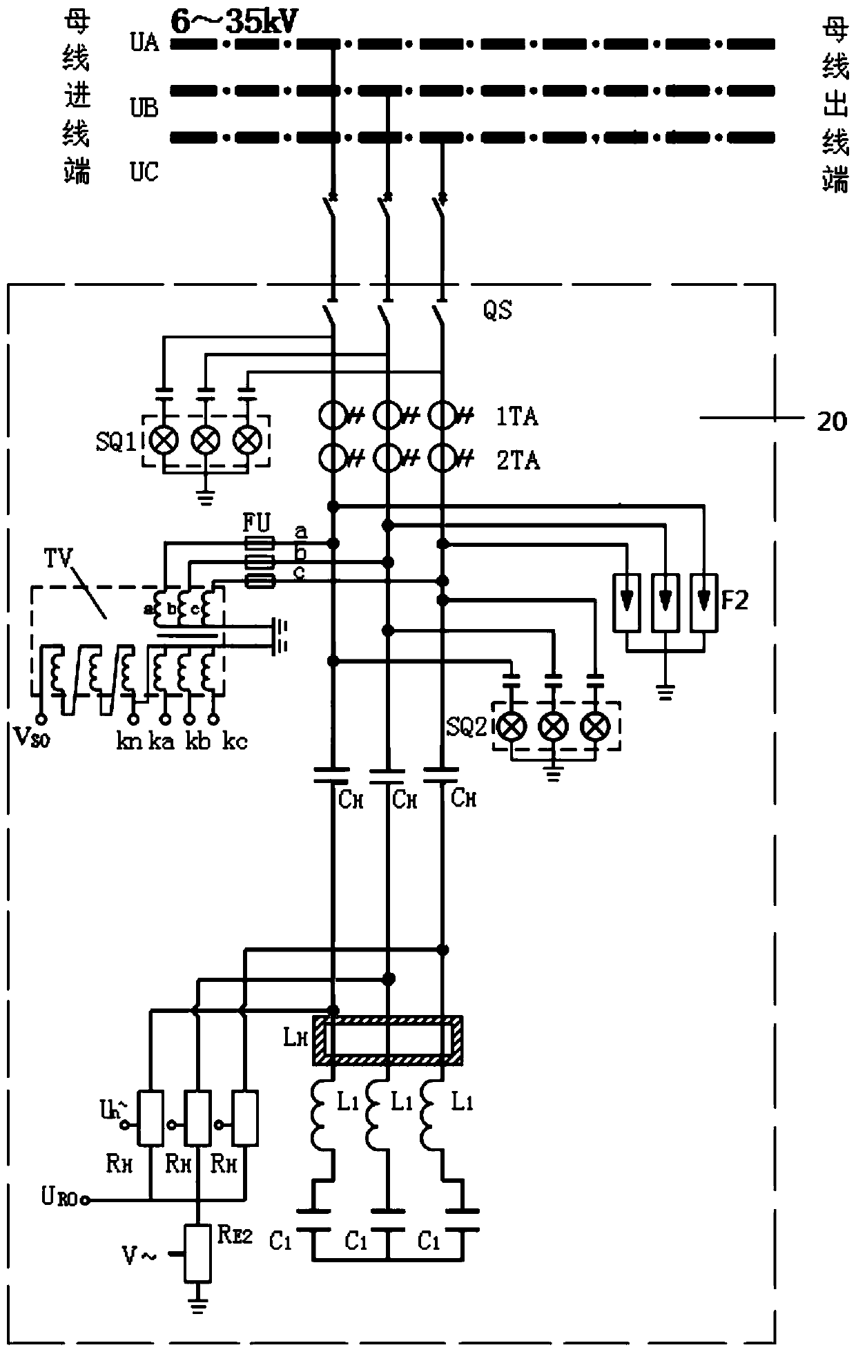
[0033] see figure 2 , the reactive power compensation device 20 of this embodiment is a three-phase circuit, and in each phase circuit, one side of the static contact of the isolating switch QS is respectively connected to a phase circuit of the bus bar, and the side of the moving contact is connected in series with the current mutual inductance Devices 1TA, 2TA, filter capacitor C H , series reactor L 1 with compensation capacitor C 1 , and the compensation capacitance C of each phase circuit 1 A common star connection is made at the end of the branch. Wherein, the current transformers 1TA and 2TA both include a primary coil and a secondary coil, and the primary coil of the current transformer is connected in series with the phase circuit isolating switch QS and the filter capacitor C H Between, the secondary coil of the current transformer induces the current of the primary coil and outputs a signal, which can be used to measure the current signal current or provide a c...

Embodiment 2

[0088] On the basis of Embodiment 1, the reactive power compensation device further includes a harmonic loss energy recovery unit 30, and the input terminals of the harmonic loss energy recovery unit 30 are respectively connected to the harmonics in the three-phase circuit of the reactive power compensation device. The branch through which the current flows.

[0089] With respect to the circuit structure in embodiment 1, please refer to Figure 12 , the circuit structure of the reactive power compensation device 21 used in this embodiment 2 is basically the same as that of the reactive power compensation device 20 in the previous embodiment 1, the difference is that each filter resistor R H star connection without connecting the grounding resistor R E2 and ground. The three input terminals of the harmonic loss energy recovery unit 30 are respectively connected to the filter capacitor C in each phase circuit H with the filter resistor R H between, the receive filter capacit...


PUM


Abstract

The invention provides a reactive power compensation device. The reactive power compensation device is a three-phase circuit which is connected with the three-phase bus of a power distribution network. Each phase circuit of the reactive power compensation device includes a high-pass filter resistor, a filter capacitor, a series reactor and a compensation capacitor, wherein the filter capacitor, the series reactor and the compensation capacitor are connected in series. The filter capacitor of each phase circuit of the reactive power compensation device is connected in series with the three-phase bus of the power distribution network. The compensation capacitor of each phase circuit of the reactive power compensation device is in common star connection on the tail end of the branch. One endof the high-pass filter resistor of each phase circuit of the reactive power compensation device is connected in series between the series reactor and the filter capacitor on the phase circuit, and the other end is in common star connection on the tail end of the branch. Compared with the prior art, the reactive power compensation device provided by the invention can form a C-type heterogeneous high-pass filter to filter out a variety of high-frequency harmonics without overload damage.

Description

technical field [0001] The invention relates to the field of power utilization safety of a distribution network, in particular to a reactive power compensation device for a distribution network. Background technique [0002] The existing distribution network is composed of power stations, substations and user terminals, among which, the power stations, substations and user terminals are all connected and transmitted through busbars. In the power transmission process, in order to improve the power factor of the distribution network, reduce the energy loss in the power transmission process, and ensure the energy transmission efficiency of the distribution network, reactive power compensation devices are usually connected to the distribution network. At the same time, in the existing distribution network, the non-linear loads connected to the distribution network cause harmonics in the distribution network, and the existence of harmonics can easily lead to damage to power equip...

Claims


Application Information

Patent Timeline
Patent Type & Authority Applications(China)
IPC IPC(8): H02J3/18H02J3/01H02H9/04
CPCH02H9/04H02J3/01H02J3/1821Y02E40/30Y02E40/40
Inventor 刘蔚然李清远侯永革杨凝杨杰林严伟洋邱映双
Owner 韶关市佰瑞节能科技有限公司
Why Eureka
Try Eureka