
Inverter driving system with ultra-low switching power consumption and ultra-low output end electromagnetic interference

An electromagnetic interference and inverter drive technology, which is applied in the field of frequency converters, can solve the problems of increased filter size, increased switching loss, increased system weight and cost, etc., and achieves the effect of reducing shielding requirements and ultra-low electromagnetic interference

Active Publication Date: 2020-01-14
周衍
View PDF8 Cites 0 Cited by
  • Summary
  • Abstract
  • Description
  • Claims
  • Application Information

AI Technical Summary

Problems solved by technology

In the case of the same output power, when using a lower switching frequency, the size of the filter will be greatly increased, and when using a higher switching frequency, the switching loss generated by the power switching device will also increase at the same time
At the same time, it not only increases the weight and cost of the system, but also creates problems such as additional reactive power and grounding resistance of the wire shield

Method used


Image

  • Inverter driving system with ultra-low switching power consumption and ultra-low output end electromagnetic interference
  • Inverter driving system with ultra-low switching power consumption and ultra-low output end electromagnetic interference
  • Inverter driving system with ultra-low switching power consumption and ultra-low output end electromagnetic interference

Examples


Embodiment Construction

[0054] In order to make the technical means, creative features, goals and effects achieved by the present invention easy to understand, the following will further explain how the present invention is implemented in conjunction with the accompanying drawings and specific implementation methods.

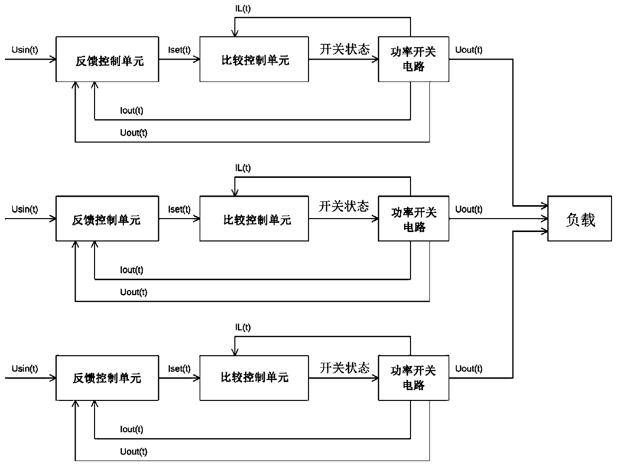
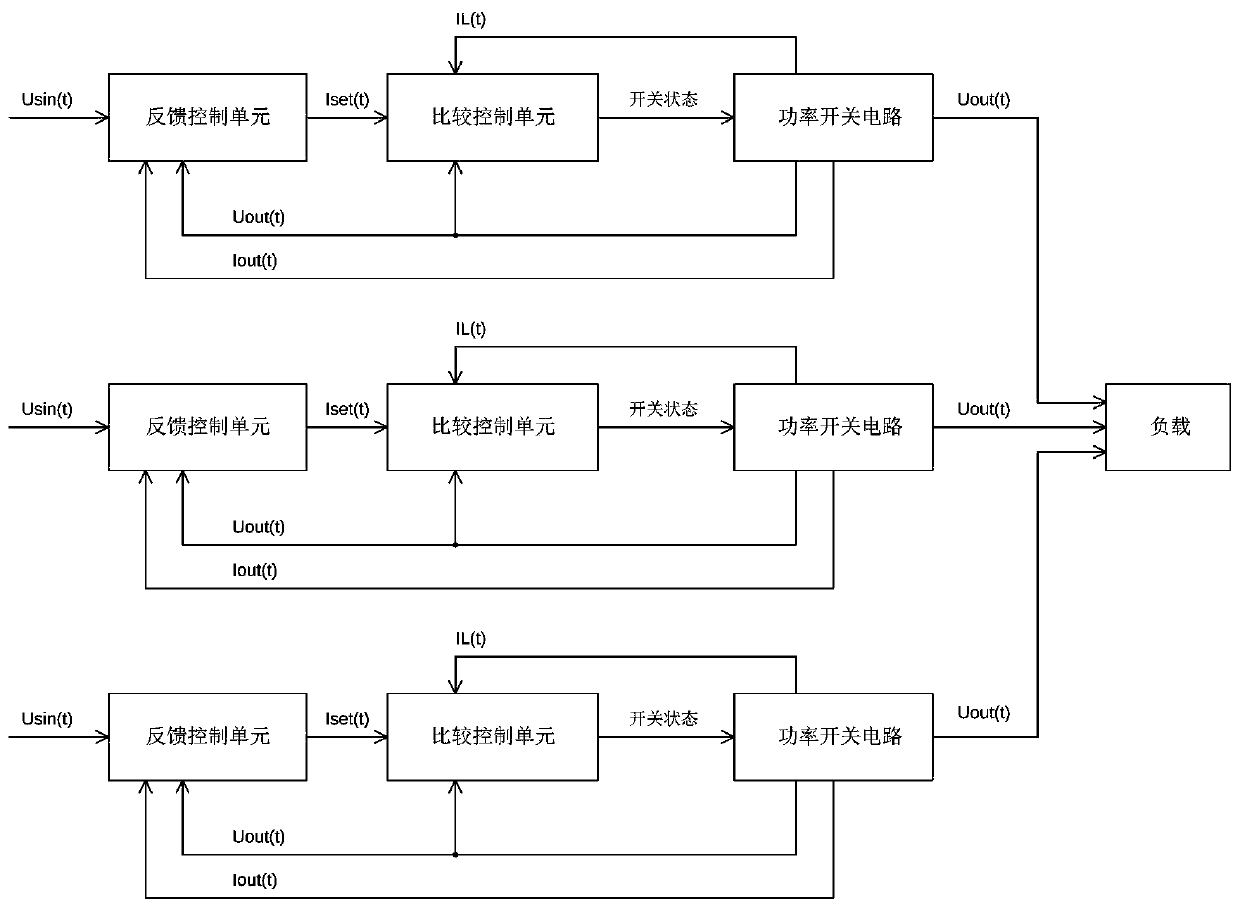
[0055] Such as Figure 1a As shown, the present invention provides an inverter drive system with ultra-low switching power consumption and ultra-low output terminal electromagnetic interference, including a multi-phase inverter drive system, such as a three-phase inverter drive system; each phase inverter drive system is Independent system, the output terminal of each phase inverter drive system is the required output AC waveform, such as sinusoidal AC, the output terminal is connected to an external load, such as the load can be a motor; each phase inverter drive system includes the following parts: feedback control unit, comparison control unit and power switch circuit;

[0056] Eac...


PUM


Abstract

The invention discloses an inverter driving system with ultra-low switching power consumption and ultra-low output end electromagnetic interference, and the system comprises a multi-phase inverter driving system, wherein each phase inverter driving system is an independent system and comprises the following parts: a feedback control unit, a comparison control unit and a power switching circuit. According to the invention, a power switching device is combined with an inductance-capacitance output circuit, so the power switching circuit is enabled to work in a state similar to a boundary transmission mode BCM, and an inductive current is enabled to be increased from a reverse switching current to a peak current and then reduced to a reverse switching current in each high-frequency switchingperiod while low-frequency sine voltage and current output is maintained at the output end. Sinusoidal voltage circuit output with low and higher harmonic components is provided in principle, and meanwhile, the average value of inductive current and inductive current of the inductor is opposite at the beginning and the end of each switching period, so that ZVS switching of the power switching device can be realized through the current, and low switching loss and low-output-end high-frequency electromagnetic interference are realized.

Description

technical field [0001] The invention relates to the technical field of frequency converters, in particular to an inverter drive system with ultra-low switching power consumption and ultra-low electromagnetic interference at output terminals. Background technique [0002] In a conventional inverter drive system, since the inverter modulates the output through high-frequency switching, the switching process produces extremely high du / dt at the output end, which will generate a large common mode through the parasitic capacitance of cables and motor windings to the ground interference. Therefore, sinusoidal filters or shielded power cables are required in applications with long distances and sensitive to electromagnetic interference. In the case of the same output power, the size of the filter will increase significantly when using a lower switching frequency, and the switching loss generated by the power switching device will also increase simultaneously when using a higher sw...

Claims


Application Information

Patent Timeline
Patent Type & Authority Applications(China)
IPC IPC(8): H02M7/48H02M1/44
CPCH02M1/44H02M7/48H02M1/0009H02M1/0058Y02B70/10
Inventor 周衍
Owner 周衍
Learn More