
Electromagnetic separation device for treating solid garbage

A solid waste, magnetic separation device technology, applied in solid separation, magnetic separation, combustion methods and other directions, can solve the problems of reducing the reliability and service life of magnetic separation equipment, wasting energy, etc., to extend life and trouble-free working time, Cost reduction and energy saving effect

Pending Publication Date: 2020-01-17
CHONGQING UNIVERSITY OF SCIENCE AND TECHNOLOGY
View PDF0 Cites 4 Cited by
  • Summary
  • Abstract
  • Description
  • Claims
  • Application Information

AI Technical Summary

Problems solved by technology

[0007] Aiming at the problem that the magnetic garbage in the existing garbage magnetic separation technology must be mechanically scraped from the strong magnetic field, which wastes energy and seriously reduces the reliability and service life of the magnetic separation equipment, an electromagnetic magnetic garbage collector for solid garbage was invented. The separation device avoids mechanically scraping magnetic waste from the strong magnetic field, saves energy, reduces the cost of waste sorting and treatment, prolongs the life of waste sorting equipment and trouble-free working time; in addition, it also improves the incineration of solid waste Efficiency, effectively avoiding the damage of magnetic waste to the incinerator during the incineration process, improving the service life of solid waste magnetic material processing equipment and the reliability of the production line, trouble-free working time and economic benefits

Method used


Image

  • Electromagnetic separation device for treating solid garbage
  • Electromagnetic separation device for treating solid garbage
  • Electromagnetic separation device for treating solid garbage

Examples


Embodiment Construction

[0024] The structure, principle and working process of the present invention will be further described below in conjunction with the accompanying drawings.

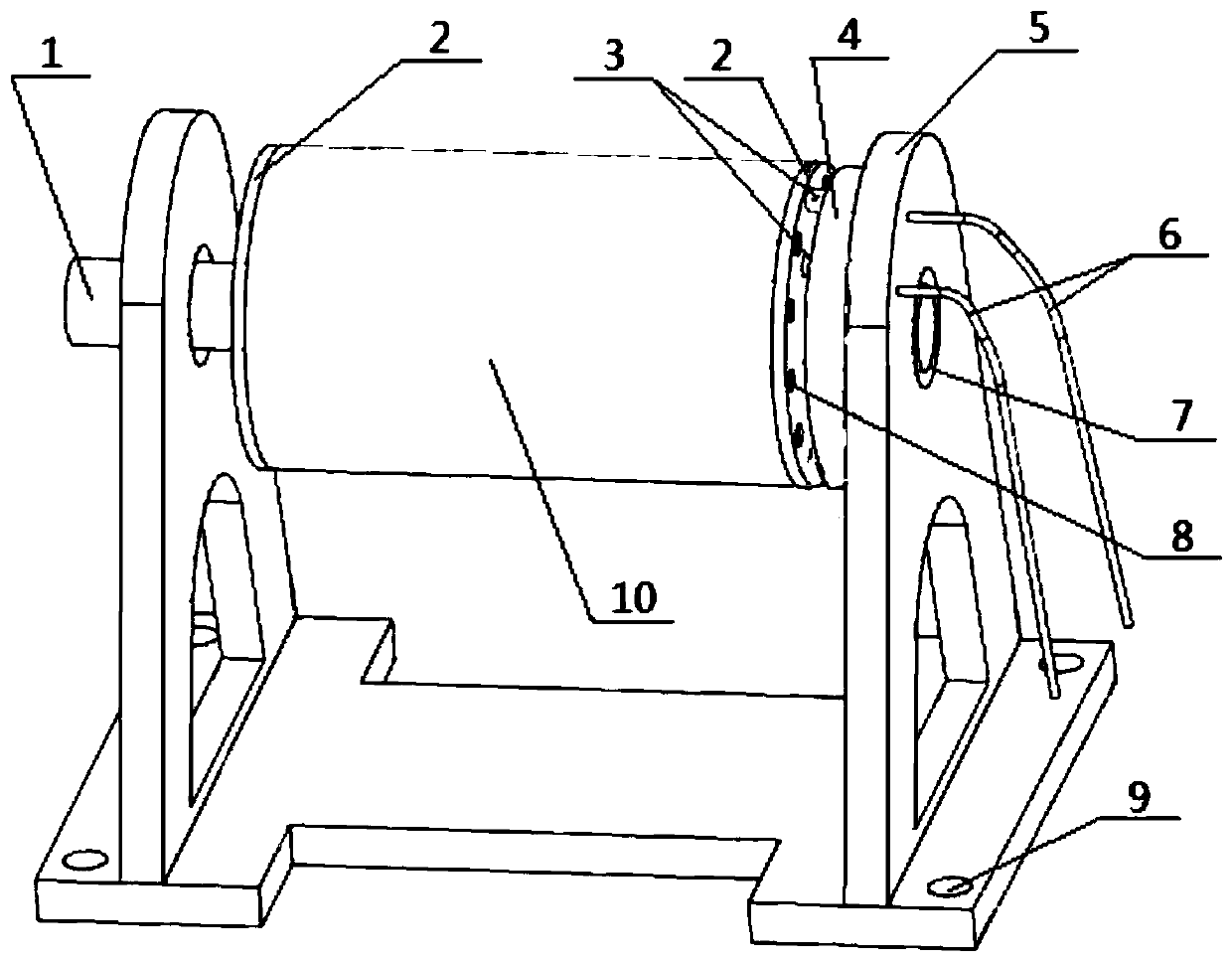
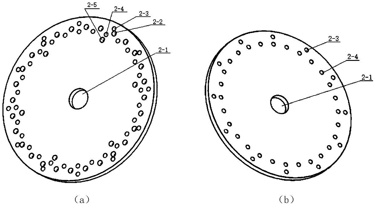
[0025] Figure 1-7 It is a structural schematic diagram of an electromagnetic magnetic separation device for treating solid waste provided by the present invention, including a power input shaft (1), an end plate flange (2), a carbon brush electrode (3), and an electrode supply plate (4) , support (5), magnet assembly (8) and magnetic separation drum (10), etc.; the magnet assembly (8) mainly includes electrode leads (8-1), connecting shaft (8-2), coil (8-3) and iron core (2-4); described magnet assembly (8) is fixed on the connecting shaft (8-2), and the connecting shaft (8-2) at its two ends is respectively connected with the end plate at the two ends of the magnetic separation drum (10) The flange (2) is fixedly connected; the end plate flange (2), the flange shaft mounting hole (2-1), the magnetic separation drum (10...


PUM


Abstract

The invention provides an electromagnetic separation device for treating solid garbage. The electromagnetic separation device comprises a support, a magnet assembly, an end plate flange, a power supply polar plate, a carbon brush electrode, a power input shaft, a magnetic separation roller and the like. The magnet assembly mainly comprises an electrode lead, a connecting shaft, a coil and an ironcore and is fixedly connected with end plate flanges at the two ends of the magnetic separation roller through the connecting shafts at the two ends. An outer electrode plate and an inner electrode plate are arranged on the power supply electrode plate; when garbage is magnetically separated, magnetic garbage is attracted to the surface of the roller through the magnetic force of the electromagnet, after the attracted magnetic garbage rotates along with the roller and passes through the partition plate, the electromagnet disappears in magnetic force due to power failure, the magnetic garbage falls into the magnetic garbage conveying belt due to the gravity effect, and separation of the magnetic garbage is achieved. According to the electromagnetic separation device, energy is saved, the garbage sorting and treating cost is reduced, magnetic garbage is prevented from being mechanically scraped off from a high-intensity magnetic field, damage of the magnetic garbage to the incinerator isavoided, the incineration efficiency of solid garbage is improved, the service life of solid garbage magnetic separation equipment is prolonged, and the reliability and economic benefits of a production line are improved.

Description

technical field [0001] The invention relates to an electromagnetic magnetic separation device for treating solid waste, in particular to an electromagnetic magnetic separation device, which is mainly used for pretreatment of magnetic materials in solid waste, etc., which can prevent magnetic waste from damaging the incinerator during incineration and prolong the solid waste. Garbage magnetic separation equipment has a longer service life and saves energy. [0002] technical background [0003] Solid waste refers to the solid waste produced by people in daily life. It has complex components, various types, and different sizes. If it is not disposed of in time, it will greatly pollute the environment and endanger human health. At the same time, it will also occupy and pollute a large amount of land resources. . The existing solid waste treatment mainly includes sanitary landfill, composting and incineration. At present, the sanitary landfill treatment method accounts for abou...

Claims


Application Information

Patent Timeline
IPC IPC(8): B03C1/12F23G5/02
CPCB03C1/12F23G5/02
Inventor 黎泽伦董立立周传德吕中亮何高法王晓梅董秋生
Owner CHONGQING UNIVERSITY OF SCIENCE AND TECHNOLOGY
Learn More