Cage rolling machine

A rolling cage machine and rolling cage technology, applied in the field of rolling cage machine, can solve the problems of low stirrup efficiency and poor stirrup effect, and achieve the effects of improving quality, facilitating guidance, and increasing stability

Pending Publication Date: 2020-01-17
CHINA CONSTR SEVENTH ENG DIVISION CORP LTD
View PDF0 Cites 0 Cited by
  • Summary
  • Abstract
  • Description
  • Claims
  • Application Information

AI Technical Summary

Problems solved by technology

[0004] The invention proposes a rolling cage machine, which is used to solve the problems of low stirrup efficiency and poor stirrup effect existing in the reinforcement cage skeleton in the prior art during the stirrup process

Method used


Image

  • Cage rolling machine
  • Cage rolling machine
  • Cage rolling machine

Examples


specific Embodiment

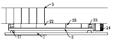
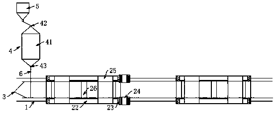
[0028] Such as Figure 1-4 As shown, the rolling cage machine includes a moving device for carrying the steel cage skeleton and driving it to walk and a wire-releasing device for straightening the winding ribs 6. The moving device includes a guide rail 1 and a channel steel support 2, and the channel steel support 2 The pulley 21 installed at its lower end moves along the guide rail 1, and the two sides of the channel steel bracket 2 are provided with rollers 22 in parallel. A structure in which the steel cage skeleton is driven to rotate by the roller 22;

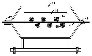
[0029] The pay-off device includes a wire guide 5 for guiding the coiled winding ribs 6 and a straightening machine 4 for straightening the winding ribs 6, and the winding ribs 6 are spirally wound through the wire guides 5 and the straightening machine 4 in turn. The structure outside the steel cage skeleton on the channel steel support 2.

[0030] The two drums 22 are connected by a transmission belt 25. There can be t...


PUM


Abstract

The invention provides a cage rolling machine, and relates to the field of processing of steel reinforcement cages. The cage rolling machine comprises a moving device and a pay-off device, wherein themoving device is used for bearing a steel reinforcement cage framework and driving the steel reinforcement cage framework to walk, and the pay-off device is used for straightening a wound bar; the moving device comprises a guide rail and a channel steel bracket; the channel steel bracket moves along the guide rail through pulleys arranged at the lower end of the channel steel bracket; rollers arearranged on the two sides of the channel steel bracket in parallel and are connected with motors through rolling shafts; the motors drives the rollers to rotate through the rolling shafts; and the paying-off device comprises a guide part and a straightening machine, wherein the guide part is used for guiding the coiled wound bar, and the straightening machine is used for straightening the wound bar. The cage rolling machine is used for solving the problems that in the prior art, in the stirrup process of a reinforcement cage framework, the stirrup efficiency is relatively low, and the stirrupeffect is poor.

Description

technical field [0001] The invention relates to a rolling cage machine. Background technique [0002] Modern prefabricated buildings include factories, warehouses, residences, railway buildings, bridges, etc., and refer to buildings assembled on site with prefabricated components. The advantage of this kind of building is that the construction speed is fast, it is less restricted by climatic conditions, it saves labor and can improve the construction quality. In the construction of bridges, culverts or high-rise buildings, the foundation may be required to be piled according to requirements. The method is to use machine punching and water mill drilling, and the hole depth meets the design requirements, and then lower the reinforcement cage to the pile hole, and then insert the conduit for concrete pouring . The stirrups in the reinforcement cage are used to meet the shear strength of the oblique section, and to connect the main reinforcement in the stressed area and the re...

Claims


Application Information

Patent Timeline
IPC IPC(8): B21F27/12B21F1/02B21F23/00
CPCB21F27/121B21F1/02B21F23/00
Inventor 宋闻辉刘会超张中善
Owner CHINA CONSTR SEVENTH ENG DIVISION CORP LTD
Why Eureka
Try Eureka