
3D printing working box device and 3D printing device

A 3D printing and workbox technology, applied in the field of 3D printing, can solve the problems of low printing efficiency and large floor space, and achieve the effect of reducing floor space and improving printing work efficiency

Pending Publication Date: 2020-01-17
KOCEL INTELLIGENT FOUNDRY IND INNOVATION CENT CO LTD
View PDF0 Cites 0 Cited by
  • Summary
  • Abstract
  • Description
  • Claims
  • Application Information

AI Technical Summary

Problems solved by technology

[0003] Based on this, it is necessary to provide a 3D printing work box device and a 3D printing machine with a small footprint and high printing efficiency to solve the problems of large footprint and low printing efficiency of the work box device of the sand mold 3D printing equipment in the prior art. printing device

Method used


Image

  • 3D printing working box device and 3D printing device
  • 3D printing working box device and 3D printing device
  • 3D printing working box device and 3D printing device

Examples


Embodiment Construction

[0018] In order to facilitate the understanding of the present invention, the present invention will be described more fully below with reference to the associated drawings. Preferred embodiments of the invention are shown in the accompanying drawings. However, the present invention can be embodied in many different forms and is not limited to the embodiments described herein. On the contrary, the purpose of providing these embodiments is to make the disclosure of the present invention more thorough and comprehensive.

[0019] It should be noted that when an element is referred to as being “disposed on” another element, it may be directly on the other element or there may also be an intervening element. When an element is referred to as being "connected to" another element, it can be directly connected to the other element or intervening elements may also be present. The terms "vertical", "horizontal", "left", "right", "top", "bottom", "bottom", "top" and similar expressions...


PUM


Abstract

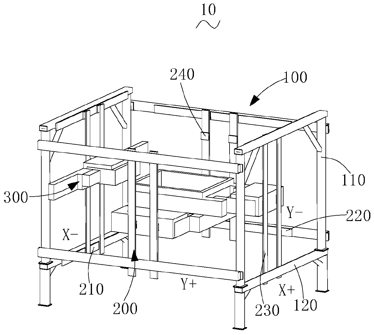
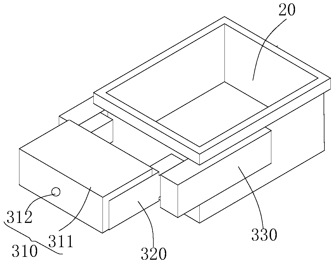
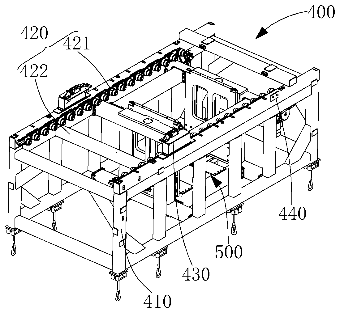
The invention relates to a 3D printing working box device and a 3D printing device. The 3D printing device comprises the 3D printing working box device. The 3D printing working box device comprises aninstalling frame, a linear movement mechanism and a plurality of grabbing mechanisms. The installing frame comprises four stand columns and two upper and lower connecting rods horizontally installedbetween every two adjacent stand columns. The linear movement mechanism comprises a plurality of X guide rail modules, a plurality of Y guide rail modules and a plurality of Z guide rail modules. TheX guide rail modules and the Y guide rail modules are installed on the connecting rods correspondingly. The Z guide rail modules are installed between every two adjacent X guide rail modules and everytwo adjacent Y guide rail modules correspondingly. Each grabbing mechanism is slidingly installed on the corresponding Z guide rail module correspondingly. The 3D printing working box device and the3D printing device are small in occupied area and high in printing efficiency.

Description

technical field [0001] The invention relates to the technical field of 3D printing, in particular to a 3D printing work box device and 3D printing equipment. Background technique [0002] The application of sand mold 3D printing technology in the foundry industry has effectively shortened the production time of castings with its efficient sand mold printing method, saved development costs, and promoted the development of R&D and design. At present, there are two types of working box devices used in sand mold 3D printing equipment: single box and flat double box. These two working box devices can meet the basic printing requirements, but there are problems such as low printing efficiency, long time consumption, and equipment occupation during the printing process. Problems such as large area lead to increased printing costs. How to optimize and improve the above-mentioned problems existing in the existing sand mold 3D printing work box device has become an urgent problem to ...

Claims


Application Information

Patent Timeline
Patent Type & Authority Applications(China)
IPC IPC(8): B22C9/02B33Y30/00
CPCB22C9/02B33Y30/00Y02P10/25
Inventor 杨保宁李佳玫何捷军
Owner KOCEL INTELLIGENT FOUNDRY IND INNOVATION CENT CO LTD
Learn More