
A polishing and grinding machine that realizes variable diameter through the cooperation of screw and bevel gear

A technology of polishing and bevel gears, applied in grinding/polishing equipment, grinding/polishing safety devices, grinding machines, etc., can solve the problems of large dead angle of grinding, low polishing efficiency of workpiece, unadjustable active radius, etc., and achieve low cost , Guarantee the polishing effect, and solve the effect of large dead angle of polishing

Active Publication Date: 2021-04-06
精海联科(宁波)智能设备有限公司
View PDF7 Cites 1 Cited by
  • Summary
  • Abstract
  • Description
  • Claims
  • Application Information

AI Technical Summary

Problems solved by technology

[0002] The active radius of the existing polishing and grinding equipment is not adjustable. When polishing and grinding workpieces with corners, small grinding knives are often replaced when grinding the corners to avoid the problem of relatively large grinding dead angles. Can lead to inefficient polishing of the workpiece

Method used


Image

  • A polishing and grinding machine that realizes variable diameter through the cooperation of screw and bevel gear
  • A polishing and grinding machine that realizes variable diameter through the cooperation of screw and bevel gear
  • A polishing and grinding machine that realizes variable diameter through the cooperation of screw and bevel gear

Examples


Embodiment Construction

[0021] The present invention will be described in further detail below with reference to the accompanying drawings and specific embodiments, but the scope of implementation of the present invention is not limited thereto.

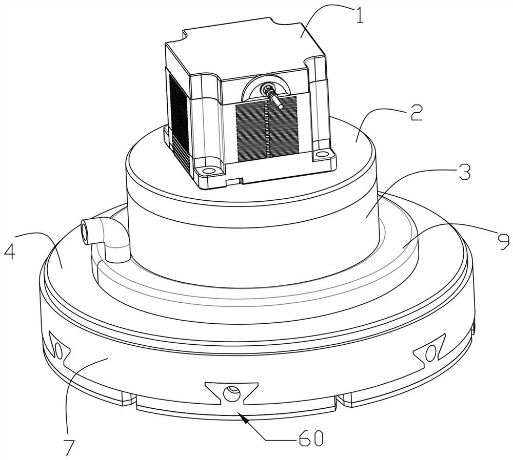
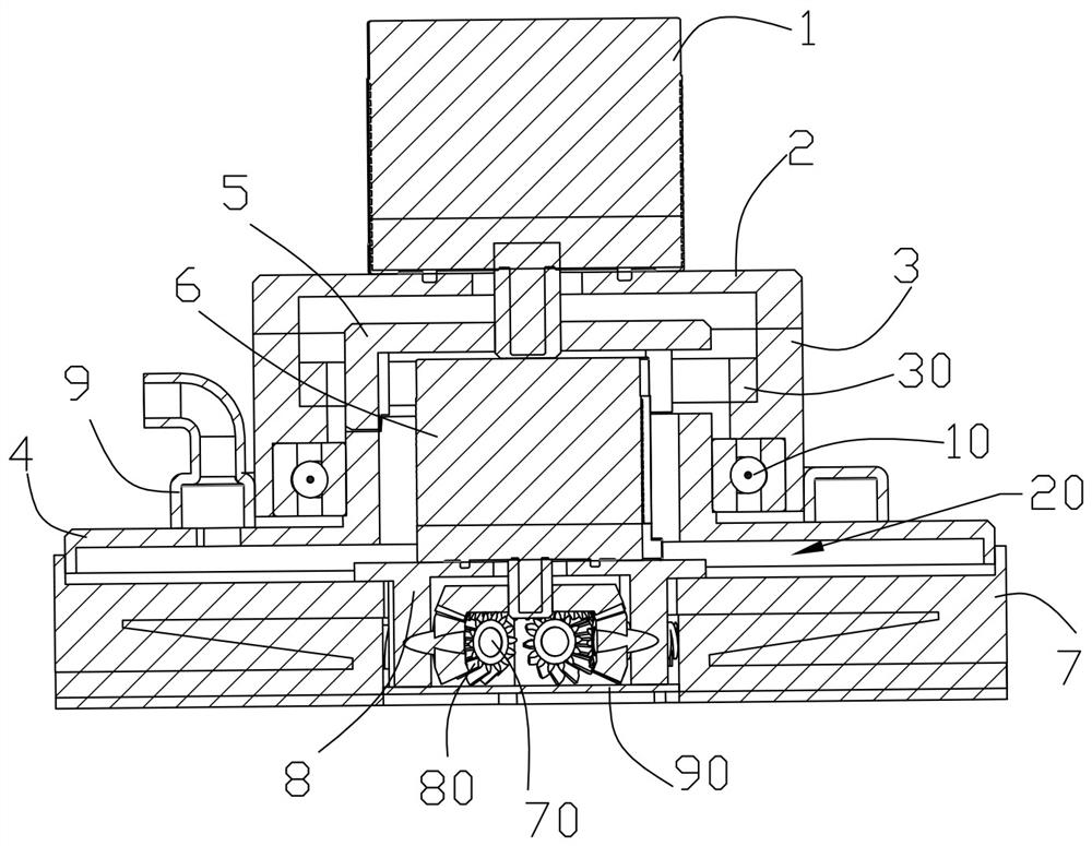
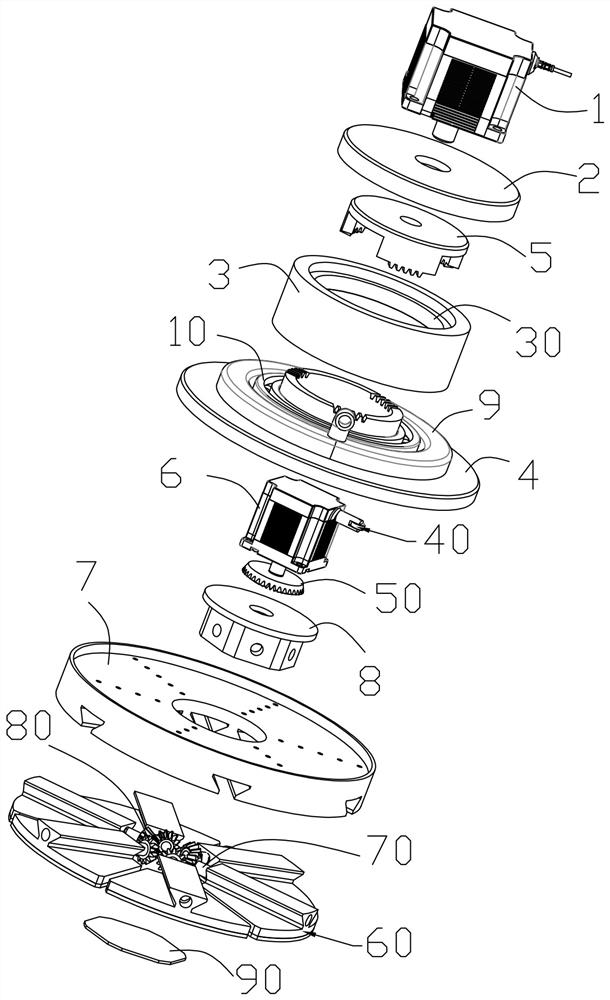
[0022] like Figure 1 to Figure 11 As shown in the figure, the polishing and grinding machine described in this embodiment, which realizes diameter reduction through the cooperation of a screw rod and a bevel gear, includes a first motor 1, a top cover 2, a cylindrical fixing sleeve 3, a dust collecting cover seat 4, an end surface Gear 5, second motor 6, grinding groove plate 7, screw fixing frame 8 and air ring 9, the first motor 1 is fixed on the top surface of the top cover 2, and its output end passes down through the top cover 2 and is connected to the end surface The middle part of the gear 5 is fixedly connected, the top cover 2 is covered on the top of the fixed sleeve 3, the dust collecting cover base 4 includes a dust collecting cover body 41 and...


PUM


Abstract

The invention discloses a polishing and grinding machine capable of changing the diameter through the cooperation of a screw and a bevel gear, which comprises a first motor, a top cover, a circular tube-shaped fixing sleeve, a dust collecting cover seat, an end gear, a second motor, and a grinding groove Disk, screw fixing frame and air ring, the dust collection cover seat is meshed with the end face gear, the fixed sleeve is connected with the dust collection connecting pipe through the bearing, a dust storage chamber is formed between the grinding groove plate and the dust collection cover seat, the air ring and the storage The dust chamber is connected, the fixed sleeve is provided with a collector ring, the second motor is electrically connected with the collector ring, the second motor is connected with the active bevel gear, the polishing groove plate is slid in the radial direction and connected with the polishing and polishing assembly, and the polishing and polishing assembly A variable-diameter screw is threaded, and the variable-diameter screw is connected with a driven bevel gear, the driven bevel gear meshes with the driving bevel gear, and the grinding groove disc is provided with a dust suction hole; the invention can realize the adjustment of the active radius of the polishing and grinding assembly, thereby It can solve the problem of relatively large grinding dead angle, high polishing efficiency and low cost.

Description

technical field [0001] The invention relates to the technical field of polishing and grinding equipment, in particular to a polishing and grinding machine that realizes diameter reduction through the cooperation of a screw rod and a bevel gear. Background technique [0002] The active radius of the existing polishing and grinding equipment is not adjustable. When polishing and grinding workpieces with corners, small grinding knives are often replaced when grinding the corners to avoid the problem of large dead corners. It will lead to low polishing efficiency of the workpiece. SUMMARY OF THE INVENTION [0003] The purpose of the present invention is to overcome the above-mentioned shortcomings, and to provide a polishing and grinding machine that realizes diameter reduction by cooperating with a screw rod and a bevel gear. [0004] For achieving the above object, the concrete scheme of the present invention is as follows: [0005] A polishing and grinding machine that re...

Claims


Application Information

Patent Timeline
Patent Type & Authority Patents(China)
IPC IPC(8): B24B27/00B24B55/00B24B55/06
CPCB24B27/0076B24B55/00B24B55/06
Inventor 陈清蓉
Owner 精海联科(宁波)智能设备有限公司
Learn More