

Rubber cutting machine
A cutting machine and rubber technology, which is applied in metal processing and other directions, can solve the problems of uneven rubber cutting and easy residual rubber liquid on the cutter, and achieve the effect of neat cutting, good cutting effect and low cutting resistance
- Summary
- Abstract
- Description
- Claims
- Application Information
AI Technical Summary
Problems solved by technology
Method used
Image

Examples
Embodiment Construction
[0023] The present invention will be described in further detail below in conjunction with the accompanying drawings.
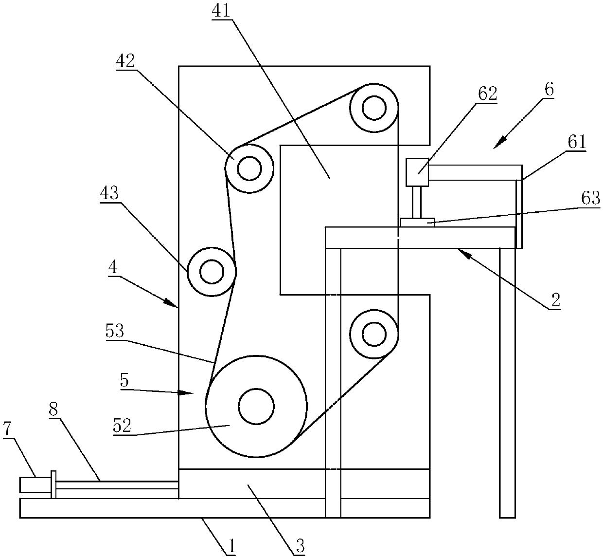
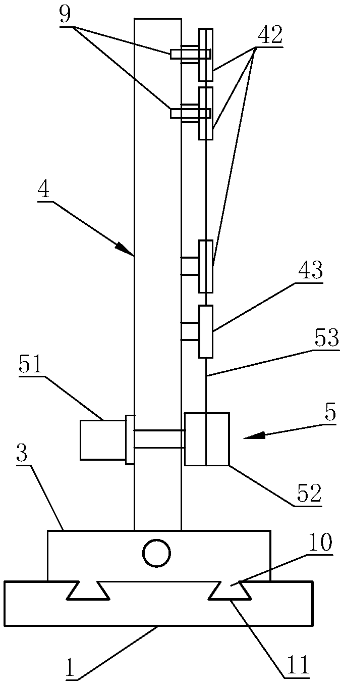
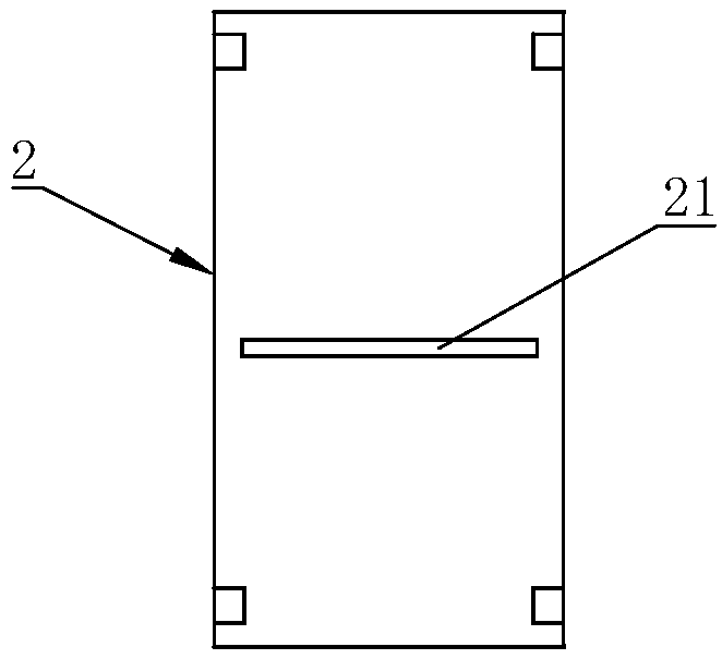
[0024] refer to figure 1 and figure 2 , the rubber cutting machine of this embodiment includes a base 1 and a cutting platform 2.
[0025] The base 1 is slidably provided with a fixed seat 3, and the fixed seat 3 is fixedly provided with a support 4. The support 4 is provided with a gap 41 corresponding to the cutting platform 2 to accommodate the cutting platform 2, and the support 4 is provided with a cutting device 5. The cutting device 5 includes a diamond wire roller 52 driven by a motor 51 to rotate. The diamond wire roller 52 is arranged at the rear end of the support 4. The diamond wire roller 52 is wound with a diamond wire 53. The support 4 is provided with at least three guide wheels 42. One of the guide wheels 42 is located above the diamond wire roller 52, and the other two guide wheels 42 are arranged at the front end of the support 4, and th...
PUM
 Abstract
Description
Claims
Application Information