Novel distributed permeable pavement and paving method

A permeable pavement, distributed technology, applied in the direction of roads, roads, pavement details, etc., to achieve the effect of reducing road surface water and easy to clean

Inactive Publication Date: 2020-01-17
HUBEI UNIV
View PDF9 Cites 1 Cited by
  • Summary
  • Abstract
  • Description
  • Claims
  • Application Information

AI Technical Summary

Problems solved by technology

[0003] In order to solve the above problems, the embodiment of the present invention provides a new type of distributed permea

Method used


Image

  • Novel distributed permeable pavement and paving method

Examples


Embodiment 1

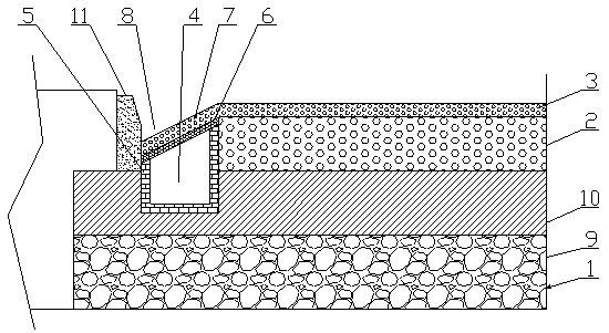
[0019] see figure 1 , the embodiment of the present invention provides a new type of distributed permeable pavement, including the pavement and the drainage ditches 4 on both sides thereof. and it is connected to the municipal drainage system through pipes or ditches. The aforementioned structure is basically consistent with the structure of the existing municipal pavement, except that the surface course 3 in this embodiment is a steel slag asphalt mixture, which is a new type of pavement surface material and has been widely used. Good water permeability and long service life and other advantages. The drainage ditch 4 penetrates the permeable layer 2 and goes deep into the base layer 1, and it is built with permeable bricks 5. The permeable bricks 5 on the inside can collect the seepage of the permeable layer 2, and the permeable bricks 5 on the outside and bottom surface can realize part of the drainage ditch. The drainage in 4 seeps outwards to meet the requirements of the...

Embodiment 2

[0027] This embodiment provides the paving method of the novel distributed permeable pavement disclosed in Embodiment 1. The method includes: paving the base layer 1 and digging trenches on both sides of the base layer 1, and using permeable bricks 5 in the ditch (three sides) A drainage ditch 4 with a certain height (it is best to ensure that the end of the orifice plate 6 close to the road surface is flush with the permeable layer 2), and the permeable layer 2 is paved on the base layer 1 and between the drainage ditch 4 on both sides, and the drainage ditch 4 The upper cover is provided with a perforated plate 6, the steel slag asphalt mixture is paved on the perforated plate 6 and the permeable layer 2, and the side ditch permeable layer 7 and the surface layer 3 are formed at the same time. The edge forms a gutter 8.

[0028] Among them, see figure 1 In the present invention, paving the base 1 and digging trenches on both sides of the base 1 include: paving the graded gr...


PUM

PropertyMeasurementUnit
Thicknessaaaaaaaaaa
Depthaaaaaaaaaa
Slopeaaaaaaaaaa

Abstract

The invention discloses a novel distributed permeable pavement and a paving method, and belongs to the technical field of municipal drainage. The novel distributed permeable pavement comprises a pavement and drainage ditches arranged at the two sides of the pavement, the pavement comprises a base layer, a permeable layer and a surface layer, and the drainage ditches are communicated with a municipal drainage system. The surface layer is made of a steel slag asphalt mixture, the drainage ditches penetrate through the permeable layer to go deep into the base layer and are built by the permeablebricks, and a drainage ditch upper cover is equipped with a pore plate. A side ditch water permeable layer is laid on the pore plate, is made of the same material as the surface layer and is obliquelyarranged downwards from the pavement to the curb to form the side ditch. The steel slag asphalt mixture with an excellent drainage effect is used as the surface layer to ensure that the accumulated water on the pavement infiltrates downwards as soon as possible so as to reduce the amount of water entering the side ditches. The pore plate and the side ditch permeable layer are laid on the drainageditches to form the side ditch to collect the accumulated water on the pavement, and the permeable bricks are built into the drainage ditches to receive the seepage water in the permeable layer to quickly drain the seepage water, so that accumulated water on the pavement is reduced. By adopting a non-rainwater grate drainage mode, the situation of drainage blockage is avoided.

Description

technical field [0001] The invention belongs to the technical field of municipal drainage, in particular to a novel distributed permeable pavement and a paving method. Background technique [0002] Based on the construction of the municipal sponge city, the municipal facilities such as roads in the city have gradually changed their original forms, and the design scheme and building materials have also changed accordingly. In the existing drainage ditches, they are all set on both sides of the road surface Ditch, and then cover the gutter with a grate with strip holes, but in reality, when the water on both sides of the road flows into the gutter, it often contains some leaves, waste paper and other sundries, these sundries After entering the drain through the grate, it will not only cause the blockage of the grate and the drain, but also be very difficult to clean. Contents of the invention [0003] In order to solve the above problems, the embodiment of the present inven...

Claims


Application Information

Patent Timeline
IPC IPC(8): E01C7/32E01C11/22
CPCE01C7/32E01C11/224E01C11/227
Inventor 陈红兵李明卢进登邓梅娥赵耀阳尹光霞李艺斐彭子芮向志欣黄紫凌
Owner HUBEI UNIV
Why Eureka
Try Eureka