An eddy current excitation adjustable magnetic pump and its working method
A magnetic pump and adjustable technology, applied in non-variable capacity pumps, components of pumping devices for elastic fluids, pumps, etc., can solve the problem of inability to adapt to various output environments, low output power, and easy fluid leakage and other problems, to avoid pollution of the environment and affect workers, reduce labor costs, and achieve the effect of strong safety
- Summary
- Abstract
- Description
- Claims
- Application Information
AI Technical Summary
Problems solved by technology
Method used
Image
Examples
Embodiment 1
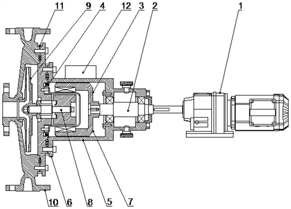
[0036] Such as Figure 1-6The eddy current excitation type adjustable magnetic drive pump shown includes: motor 1, drive shaft 2, outer magnetic rotor 3, auxiliary disk 4, first casing 5, second casing 6, inner magnetic rotor 7, linkage shaft 8. The impeller 9 and the end cover 10, the output end of the motor 1 is provided with a drive shaft 2, the output end of the drive shaft 2 is connected with an external magnetic rotor 3, and the outer side of the drive shaft 2 is provided with a first casing 5, so The first casing 5 is connected to the drive shaft 2 through a bearing, the first casing 5 is sleeved on the outside of the outer magnetic rotor 3, and a second casing 6 is fixedly arranged on one side of the first casing 5. The second casing 6 is provided with a cylindrical protrusion, the convex surface of the second casing 6 is close to the outer magnetic rotor 3, and the concave surface of the second casing 6 is provided with an inner magnetic rotor 7, and the center of the...
Embodiment 2
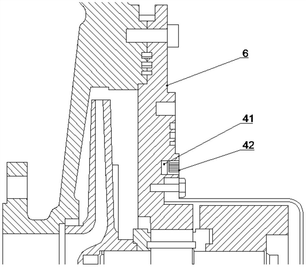
[0054] Such as figure 1 , 2 A kind of eddy current excitation type adjustable magnetic pump shown in and 3 comprises: motor 1, drive shaft 2, outer magnetic rotor 3, auxiliary disk 4, first casing 5, second casing 6, inner magnetic rotor 7, Linkage shaft 8, impeller 9 and end cover 10, the output end of the motor 1 is provided with a drive shaft 2, the output end of the drive shaft 2 is connected with an outer magnetic rotor 3, and the outer side of the drive shaft 2 is provided with a first casing 5 , the first casing 5 is connected to the drive shaft 2 through a bearing, the first casing 5 is sleeved on the outside of the outer magnetic rotor 3, and a second casing 6 is fixedly arranged on one side of the first casing 5, The second casing 6 is provided with a cylindrical protrusion, the convex surface of the second casing 6 is close to the outer magnetic rotor 3, and the concave surface of the second casing 6 is provided with an inner magnetic rotor 7, and the inner magneti...
Embodiment 3
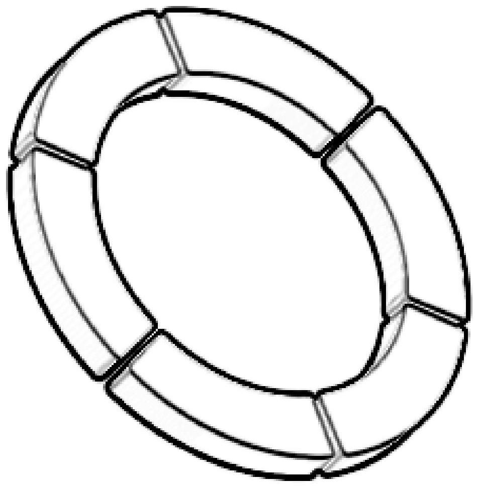
[0058] Such as figure 1 , 4 , 5 and 6 show a kind of eddy current excitation adjustable magnetic pump, including: motor 1, drive shaft 2, outer magnetic rotor 3, auxiliary disk 4, first casing 5, second casing 6, inner magnetic rotor 7. Linkage shaft 8, impeller 9 and end cover 10, the output end of the motor 1 is provided with a drive shaft 2, the output end of the drive shaft 2 is connected with an external magnetic rotor 3, and the outside of the drive shaft 2 is provided with a first machine Housing 5, the first housing 5 is connected to the drive shaft 2 through bearings, the first housing 5 is sleeved on the outside of the outer magnetic rotor 3, and a second housing is fixedly installed on one side of the first housing 5 6. The second casing 6 is provided with a cylindrical protrusion, the convex surface of the second casing 6 is close to the outer magnetic rotor 3, and the concave surface of the second casing 6 is provided with an inner magnetic rotor 7, and the inner...
PUM
 Abstract
Description
Claims
Application Information
 - R&D
- Intellectual Property
- Life Sciences
- Materials
- Tech Scout
- Unparalleled Data Quality
- Higher Quality Content
- 60% Fewer Hallucinations
Browse by: Latest US Patents, China's latest patents, Technical Efficacy Thesaurus, Application Domain, Technology Topic, Popular Technical Reports.
© 2025 PatSnap. All rights reserved.Legal|Privacy policy|Modern Slavery Act Transparency Statement|Sitemap|About US| Contact US: help@patsnap.com


