Parallel type dual-redundancy electric steering engine based on overrunning clutch

A technology of overrunning clutch and electric steering gear, which is applied in the direction of electric components, electromechanical devices, electrical components, etc., can solve problems such as steering gear failure, motor failure, plane crash, etc., and achieve high reliability, simple structure, and good maintainability Effect

Active Publication Date: 2020-01-17
XIAN FLIGHT SELF CONTROL INST OF AVIC
View PDF6 Cites 3 Cited by
  • Summary
  • Abstract
  • Description
  • Claims
  • Application Information

AI Technical Summary

Problems solved by technology

[0003] The traditional single-redundancy electric steering gear has only one transmission path from the output shaft of the motor to the output shaft of the steering gear. There are many transmission parts such as bearings, gears, and leadscrews distributed on the transmission path. Any failure of any transmission part will cause the rudder to fail. In addition, the mechanical structure of the servo motor also has single points such as the motor stator and armature. Failure will cause the motor to fail, and then cause the steering gear to fail, which will seriously affect the safety of the flight control system and the aircraft.
[0004] To sum up, the traditional single-redundancy electric steering gear has many single points in the transmission path and mechanical structure, and any single-point failure will lead to flight control failure or even a plane crash, which requires consideration of the use of redundant electric steering gear Reduce the single point to avoid the above problems, improve the safety and reliability of the steering gear and flight control system, and reduce the failure rate of the steering gear

Method used


Image

  • Parallel type dual-redundancy electric steering engine based on overrunning clutch
  • Parallel type dual-redundancy electric steering engine based on overrunning clutch

Examples


Embodiment Construction

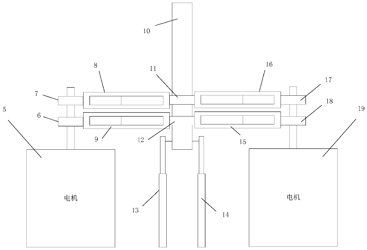
[0024] A parallel dual-redundancy electric steering gear based on an overrunning clutch, such as figure 2 shown, including:

[0025] The first servo motor 5, the second servo motor 19, the first one-way clutch 7, the second one-way clutch 17 and the third one-way clutch 12 facing the clockwise rotation of the output shaft, three facing the output shaft The fourth one-way clutch 6, the fifth one-way clutch 18, and the sixth one-way clutch 11 that rotate counterclockwise to lock, four first reduction transmission mechanisms 8 that make the rotation direction of the output shaft the same as the rotation direction of the servo motor shaft. The second reduction transmission mechanism 9 , the third reduction transmission mechanism 15 and the fourth reduction transmission mechanism 16 , the first position sensor 13 , the second position sensor 14 and the output shaft 10 are composed. The first servo motor 5 is connected with the fourth one-way clutch 6, the first one-way clutch 7 i...


PUM


Abstract

The invention belongs to the technical field of electric steering engines of a flight control system, and designs a parallel type dual-redundancy electric steering engine based on an overrunning clutch. The electric steering engine includes a first servo motor ( 5), a second servo motor(19), a first one-way clutch (7), a second one-way clutch (17), a third one-way clutch (12), a fourth one-way clutch (6), a fifth one-way clutch (18), a sixth one-way clutch (11), a first reducing transmission mechanism (8), a second reducing transmission mechanism (9), a third reducing transmission mechanism (15), a fourth reducing transmission mechanism (16), a first position sensor (13), a second position sensor (14) and an output shaft (10), wherein the first one-way clutch (7), the second one-way clutch(17) and the third one-way clutch (12) are rotationally locked clockwise towards the output shaft; the fourth one-way clutch (6), the fifth one-way clutch (18) and the sixth one-way clutch (11) are rotationally locked anticlockwise towards the output shaft; the first reducing transmission mechanism (8), the second reducing transmission mechanism (9), the third reducing transmission mechanism (15)and the fourth reducing transmission mechanism (16) make the rotation direction of the output shaft same as the rotation direction of a servo motor shaft.

Description

technical field [0001] The invention belongs to the electric steering gear technology of a flight control system, in particular to a design of a parallel dual-redundancy electric steering gear based on an overrunning clutch. Background technique [0002] figure 1 It is the structure of the current traditional single-redundancy electric steering gear, which consists of a servo motor 1, a reduction transmission mechanism 2, an output shaft 3 and a position sensor 4. The working principle is: the servo motor 1 receives the control command, drives the output shaft 3 to move through the reduction transmission mechanism 2, the output shaft 3 is fixedly connected with the position sensor 4, and the position sensor 4 feeds back the position of the steering gear so that the electric steering gear can stably follow the control command. [0003] The traditional single-redundancy electric steering gear has only one transmission path from the output shaft of the motor to the output shaf...

Claims


Application Information

Patent Timeline
Patent Type & Authority Applications(China)
IPC IPC(8): F16H1/22H02K7/116B64C13/50
CPCF16H1/22H02K7/116B64C13/50
Inventor 夏路赵建伟刘基玉梁颖茜
Owner XIAN FLIGHT SELF CONTROL INST OF AVIC
Why Eureka
Try Eureka