
High-pressure dry oil pneumatic control valve

An oil-gas and high-pressure technology, which is applied in the field of high-pressure dry oil-gas control valves, can solve problems such as poor reliability, limited electromagnetic force, and slow response speed, and achieve high reliability, fast response speed, and high-frequency work requirements.

Inactive Publication Date: 2020-01-17
HUATIAN ENG & TECH CORP MCC
View PDF5 Cites 7 Cited by
  • Summary
  • Abstract
  • Description
  • Claims
  • Application Information

AI Technical Summary

Problems solved by technology

At present, the dry oil control valve mainly adopts motor drive and electromagnet drive. The motor drive mode has a large driving force and reliable operation, but it is large in size and slow in response, which is not suitable for frequent start-up work occasions; the electromagnet drive mode has a relatively fast response speed. , but limited to the volume and power of the electromagnet, the electromagnetic force is limited, and the work reliability is poor; therefore, for some automatic lubrication occasions with high operating frequency of the control valve, it is difficult for the existing solenoid valve to meet the requirements, and it is urgent to develop a response speed Fast, reliable dry oil control valve

Method used


Image

  • High-pressure dry oil pneumatic control valve
  • High-pressure dry oil pneumatic control valve

Examples


Embodiment 1

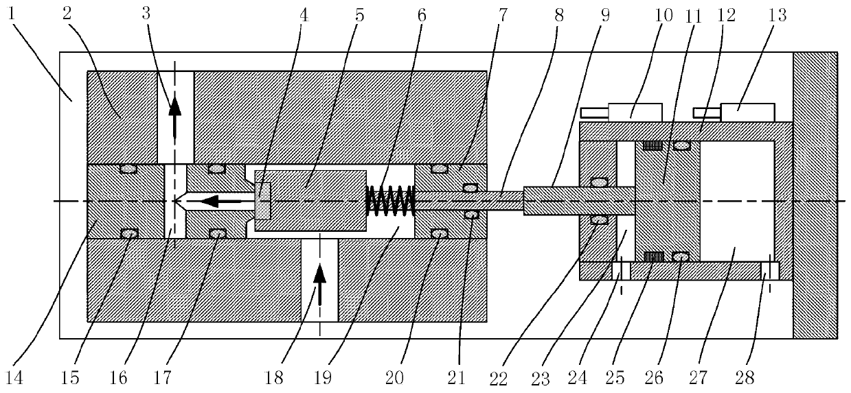
[0022] from Figure 1-2 It can be seen that a high-pressure dry oil and gas control valve in this embodiment includes a base 1, the base 1 is an L-shaped structure, the surface of the base 1 is provided with a valve body 2, and a central through hole is opened inside the valve body 2. A valve seat 14, a valve core 5 and a sealing end cap 7 are respectively arranged in the central through hole, the sealing end cap 7 is clamped in the central through hole of the valve body 2, and a fourth valve is arranged between the sealing end cap 7 and the valve body 2. The sealing ring 20, the cavity formed between the valve body 2, the valve core 5 and the sealing end cover 7 is the valve cavity 19, and the first sealing ring 15 and the second sealing ring 17 are respectively arranged between the valve seat 14 and the valve body 2 , the valve seat 14 is provided with a T-shaped through hole 16, the surface of the valve body 2 is provided with an oil outlet 3, one side of the oil outlet 3 c...


PUM


Abstract

The invention discloses a high-pressure dry oil pneumatic control valve and belongs to the technical field of mechanical lubrication control. The high-pressure dry oil pneumatic control valve comprises a base, the surface of the base is provided with a valve body, and a center through hole is formed in the valve body; a valve seat, a valve element and a sealing end cover are arranged in the centerthrough hole separately, a cavity formed among the valve body, the valve element and the sealing end cover is a valve cavity, and a T-shaped through hole is formed in the valve seat; the surface of the valve body is provided with an oil outlet and an oil inlet, a piston rod is connected to the valve element through a valve rod, and a piston is connected to one end of the piston rod. The high-pressure dry oil pneumatic control valve is compact in structure, high in response speed and high in reliability, when the piston rod is ejected out, the valve element and a sealing body of one end of thevalve element press one end of the valve seat, so that the T-shaped through hole in the valve seat is sealed, and the oil inlet is not communicated with the oil outlet; when the piston rod is drawn back, the valve cavity, the T-shaped through hole, the oil inlet and the oil outlet are in a communicated state, the operation state of the control valve is controlled accordingly, and the demand for high-frequency work of an automatic lubrication system is met.

Description

technical field [0001] The invention relates to the technical field of mechanical lubrication control, and more specifically relates to a high-pressure dry oil air control valve. Background technique [0002] The high-pressure dry oil control valve is one of the key components of the dry oil automatic lubrication system. At present, the dry oil control valve mainly adopts motor drive and electromagnet drive. The motor drive mode has a large driving force and reliable operation, but it is large in size and slow in response, which is not suitable for frequent start-up work occasions; the electromagnet drive mode has a relatively fast response speed. , but limited to the size and power of the electromagnet, the electromagnetic force is limited, and the work reliability is poor; therefore, for some automatic lubrication occasions with high operating frequency of the control valve, it is difficult for the existing solenoid valve to meet the requirements, and it is urgent to devel...

Claims


Application Information

Patent Timeline
Patent Type & Authority Applications(China)
IPC IPC(8): F16K1/00F16K31/122
CPCF16K1/00F16K31/122
Inventor 董岱杜预方田
Owner HUATIAN ENG & TECH CORP MCC
Learn More