Air valve

A technology of air valve and spool, applied in valve details, valve device, valve operation/release device, etc., can solve the problems of lower water delivery efficiency, many leakage points, too small exhaust channel, etc., and achieve simplified separation Combined structure, reliable exhaust performance, and the effect of increasing reliability

Inactive Publication Date: 2020-01-17
WATTS VALVE CHANGSHA
View PDF10 Cites 10 Cited by
  • Summary
  • Abstract
  • Description
  • Claims
  • Application Information

AI Technical Summary

Problems solved by technology

[0004] The first point is that there are problems of complex structure and many leakage points: the split combined structure is adopted for high-speed exhaust and micro-exhaust, resulting in a large volume of the product, taking up a lot of space, and its complex structure and many leakage points
[0005] The second point is that there is a problem that cannot be adjusted: the designed exhaust channel is too small and cannot be adjusted according to the working conditions. When there is negative pressure in the pipeline, a large amount of gas cannot be quickly replenished
[0006] The third point is that it does not have the function of anti-blowing and blocking: when the high-pressure airflow in the pipeline is quickly discharged, the valve core with a small movement range will easily cause the valve to blow and block in the exhaust passage, forming an air bag embolism, which greatly reduces the water delivery efficiency
[0007] Fourth, it does not have anti-jamming function: its floating ball and sealing pair are in direct contact with the fluid medium, and dirt is easy to enter, causing the channel to be blocked
[0008] Fifth point, there is no signal feedback function: because there is no detection device, when the air valve is in an abnormal state, the alarm cannot be reported to the field technicians in time, resulting in damage to the pipeline

Method used


Image

  • Air valve
  • Air valve
  • Air valve

Examples


Embodiment Construction

[0035] In order to make the objectives, technical solutions, and advantages of the embodiments of the present invention clearer, the technical solutions in the embodiments of the present invention will be described clearly and completely in conjunction with the accompanying drawings in the embodiments of the present invention. Obviously, the described embodiments It is a part of the embodiments of the present invention, not all the embodiments. The components of the embodiments of the present invention generally described and illustrated in the drawings herein may be arranged and designed in various different configurations. Therefore, the following detailed description of the embodiments of the present invention provided in the accompanying drawings is not intended to limit the scope of the claimed invention, but merely represents selected embodiments of the present invention.

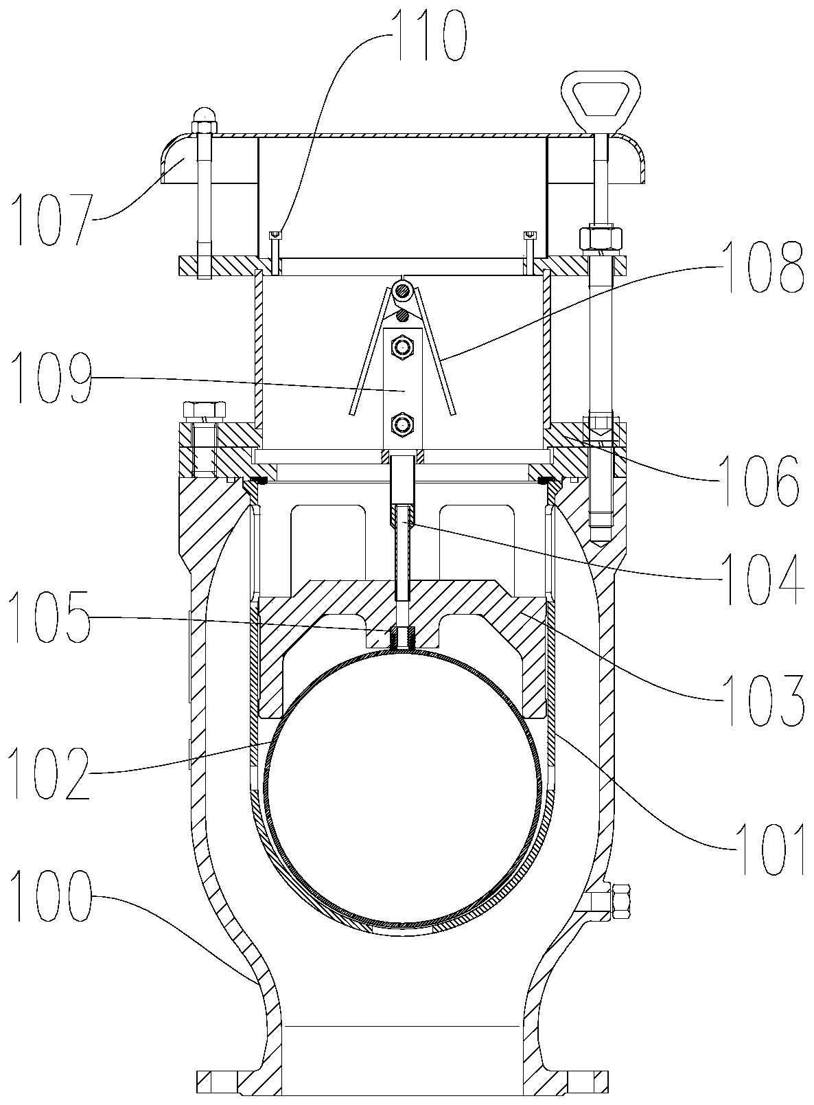
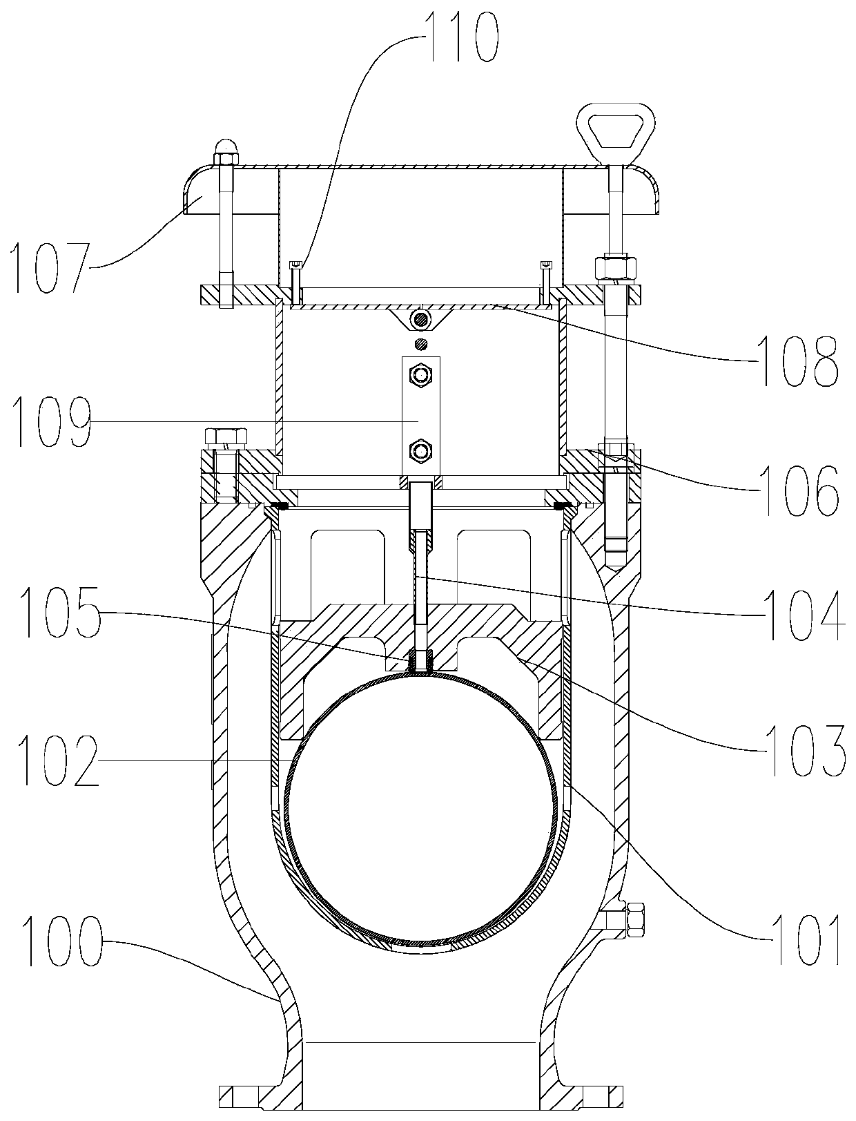
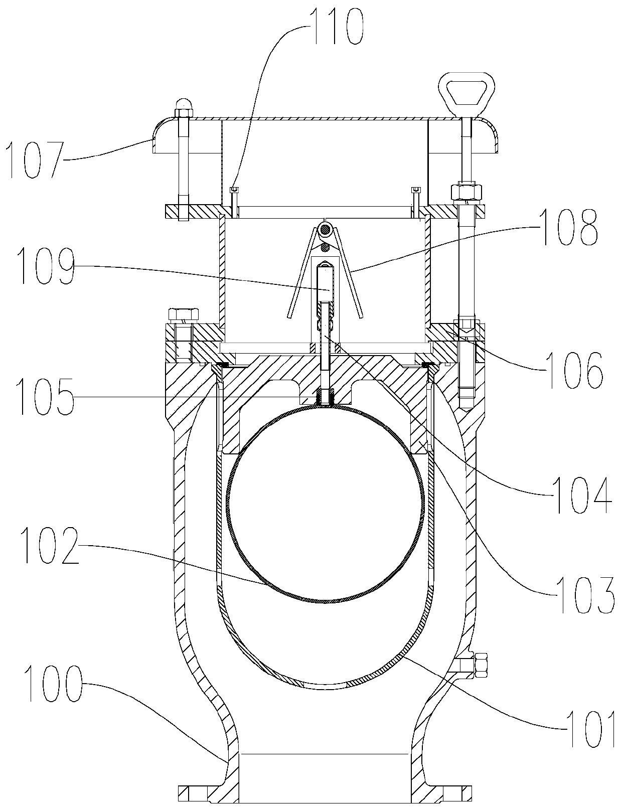
[0036] Reference Figure 1 ~ Figure 5 , The present invention discloses an air valve, including a va...


PUM


Abstract

The invention discloses an air valve. The air valve comprises a valve body, wherein a valve cavity with a bottom opening is formed in the valve body, a rapid exhaust passage communicating with the valve cavity is arranged at the upper end of the valve body, a valve element mechanism capable of moving up and down is arranged in the valve cavity, the rapid exhaust passage can be closed or opened inthe process of moving up or down of the valve element mechanism, and a signal feedback device used for detecting a signal of the movement position of the valve element mechanism is arranged in the rapid exhaust passage. According to the air valve, through the signal feedback device arranged in the rapid exhaust passage and used for detecting the signal of the movement position of the valve elementmechanism, real-time monitoring of the movement position of the valve element mechanism is achieved, and timely feedback is sent to a technician when a problem occurs, so that the condition that timely processing cannot be achieved after the valve element mechanism is stuck is avoided.

Description

Technical field [0001] The invention belongs to the technical field of valves, and specifically relates to an air valve. Background technique [0002] In the process of pipeline water transportation, the locations including the pump outlet pipe, the local high point of the long-distance water pipeline, the long horizontal section, the long upslope section, and the end of the horizontal section need to be equipped with air valves to ensure high speed when filling water When exhausting and filling the pipe, the gas precipitated in the water is discharged in a small amount. At the same time, it can be quickly inhaled when the pipe is emptied to prevent the pipeline from forming negative pressure and damaging the pipeline, thereby improving the water delivery efficiency and protecting the smooth operation of the pipeline. [0003] The air valves currently on the market have the following problems: [0004] The first point is that there is a problem of complex structure and many leakage ...

Claims


Application Information

Patent Timeline
Patent Type & Authority Applications(China)
IPC IPC(8): F16K31/22F16K24/02F16K37/00
CPCF16K24/02F16K31/22F16K37/0041
Inventor 张波陈楚天胡俊杰童成彪柳孝清胡姗黎任杰陈建辉狄词平
Owner WATTS VALVE CHANGSHA
Why Eureka
Try Eureka