Lamp structure

A technology of lamps and card slots, applied in gardening tools/equipment, lighting and heating equipment, applications, etc., can solve the problems of glue temperature, humidity influence, troublesome installation and disassembly, uniform arrangement of unfavorable light sources, etc., to prevent deformation and occupation small area effect

Pending Publication Date: 2020-01-17
FUJIAN SANAN SINO SCI PHOTOBIOTECH CO LTD
View PDF0 Cites 1 Cited by
  • Summary
  • Abstract
  • Description
  • Claims
  • Application Information

AI Technical Summary

Problems solved by technology

The fixing method of riveting and screw locking is adopted. If a metal reflector is used, a sufficient safety distance needs to be reserved on the light source board, which is not conducive to the uniform arrangement of the light source, and the installation and disassembly are more troublesome; the groove is inserted and the shell is buckled. Fixing a lamp with a reflector cannot achieve a simple structure, and it cannot be flexibly applied to reflectors of different angles; it is fixed by glue, and the glue used is easily affected by temperature and humidity, and it is prone to aging and falling off after long-term use

Method used


Image

  • Lamp structure
  • Lamp structure
  • Lamp structure

Examples


Embodiment 1

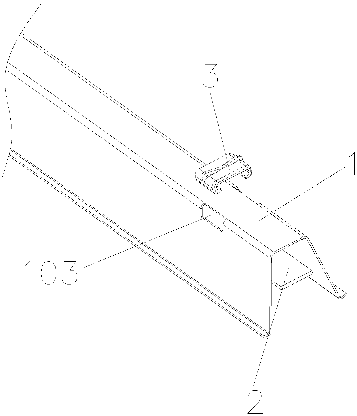
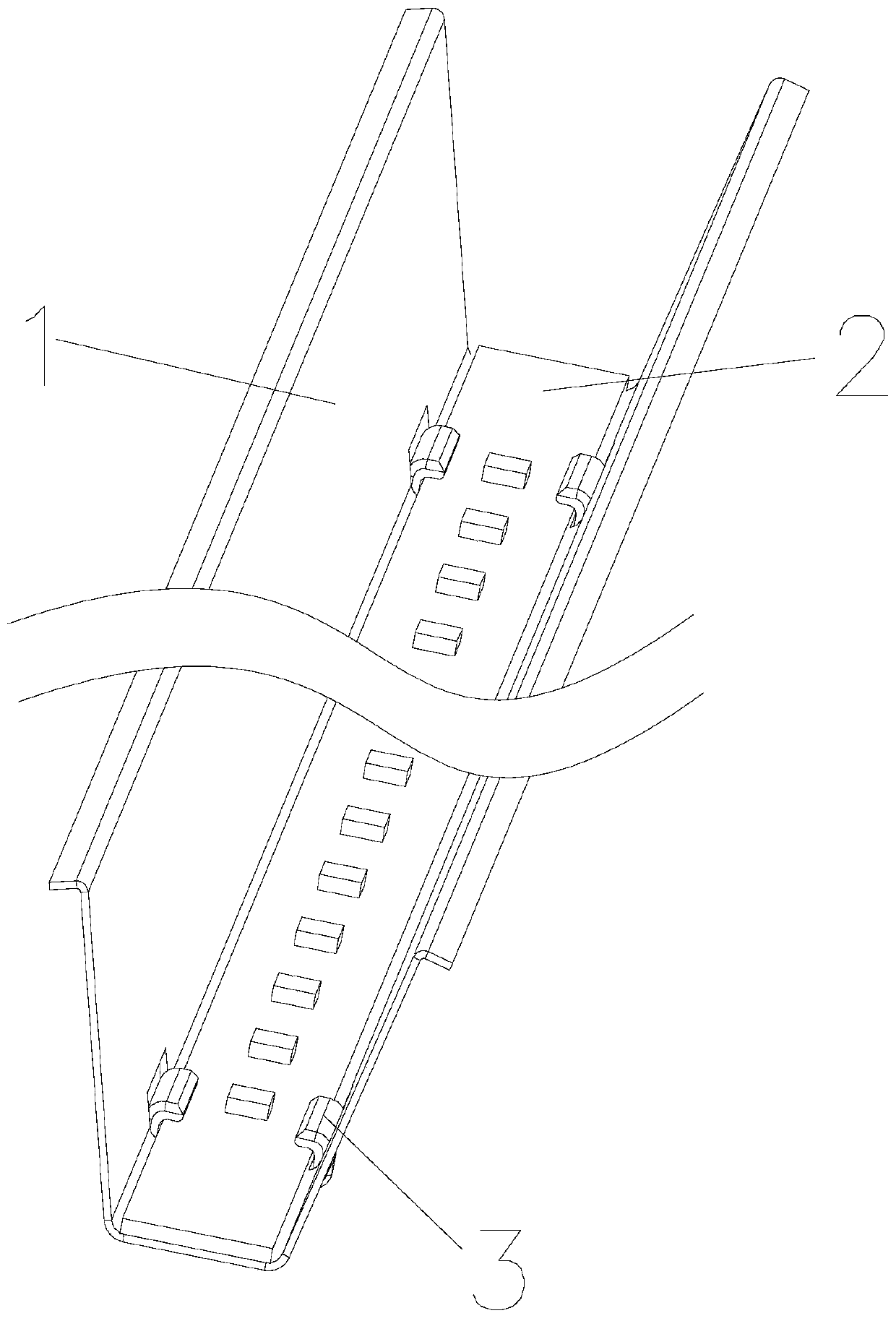
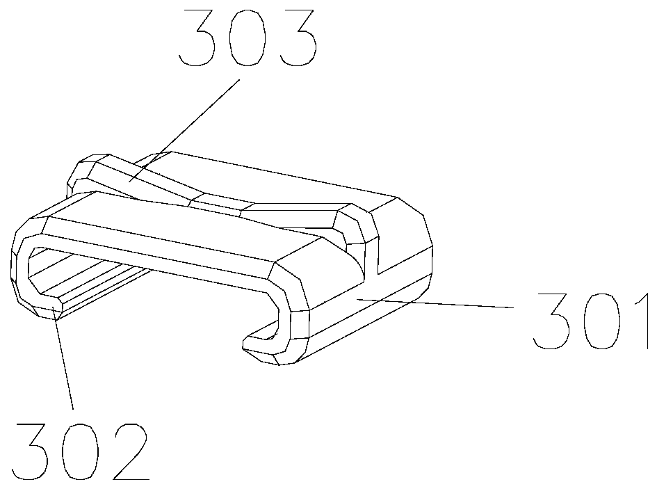
[0038] see Figure 1-Figure 6 , a light fixture structure in this embodiment, including a reflector 1 and a light source board 2, and also includes a detachable buckle device 3 with at least two clamping edges 301, and at least two buckles for installing on the reflector 1 The clamping groove 103 of the device 3 , the clamping edge 301 of the clamping device 3 is inserted into the clamping groove 103 , and the light source board 2 is fixed between the clamping edge 301 and the gap formed between the reflecting surface of the reflector 1 . Specifically, the ends of the two card edges 301 of the buckle device 3 are respectively provided with a card point 302 for fixing the light source board 2 to prevent the light source board 2 from falling off. In other embodiments, the ends of the two card edges 301 are respectively provided with The fixed positions of the two clamping points 302 are more flexible and adjustable, which are not shown in the drawings. The card slot 103 is a ca...

Embodiment 2

[0043] see Figure 1-Figure 5 , Figure 7, a light fixture structure in this embodiment, including a reflector 1 and a light source board 2, and also includes a detachable buckle device 3 with at least two clamping edges 301, and at least two buckles for installing on the reflector 1 The clamping groove 103 of the device 3 , the clamping edge 301 of the clamping device 3 is inserted into the clamping groove 103 , and the light source board 2 is fixed between the clamping edge 301 and the gap formed between the reflecting surface of the reflector 1 . Specifically, the ends of the two card edges 301 of the buckle device 3 are respectively provided with a card point 302 for fixing the light source board 2 to prevent the light source board 2 from falling off. In other embodiments, the ends of the two card edges 301 are respectively provided with The fixed positions of the two clamping points 302 are more flexible and adjustable, which are not shown in the drawings. The card slot...

Embodiment 3

[0048] see Figure 1-Figure 5 , Figure 8 , a light fixture structure in this embodiment, including a reflector 1 and a light source board 2, and also includes a detachable buckle device 3 with at least two clamping edges 301, and at least two buckles for installing on the reflector 1 The clamping groove 103 of the device 3 , the clamping edge 301 of the clamping device 3 is inserted into the clamping groove 103 , and the light source board 2 is fixed between the clamping edge 301 and the gap formed between the reflecting surface of the reflector 1 . Specifically, the ends of the two card edges 301 of the buckle device 3 are respectively provided with a card point 302 for fixing the light source board 2 to prevent the light source board 2 from falling off. In other embodiments, the ends of the two card edges 301 are respectively provided with The fixed positions of the two clamping points 302 are more flexible and adjustable, which are not shown in the drawings. The card slo...


PUM


Abstract

The invention relates to the technical field of LED plant growth lamps, particularly relates to a lamp structure. The lamp structure comprises a reflector and a light source plate, and further comprises a detachable buckling device with at least two clamping edges, the reflector is provided with at least two clamping grooves used for installing the buckling devices, the clamping edges of the buckling devices are embedded into the clamping grooves, and the light source plate is fixed between gaps formed between the clamping edges and the reflecting surface of the reflector. By arranging the detachable buckling device, the buckling device directly penetrates through the clamping groove in the reflector to directly fix the light source plate to the reflector, operation is convenient, the light source plate can be directly buckled, and the reflector with different light distribution angles can be installed according to requirements.

Description

technical field [0001] The invention relates to the technical field of LED plant growth lamps, in particular to a lamp structure. Background technique [0002] LED plant growth lamp is an artificial light source that uses LED as the illuminant and uses a special spectrum to meet the lighting conditions required for plant photosynthesis. The light source of plants can be customized and adjusted, which improves the growth speed of plants and other advantages. [0003] The following problems exist in the prior art. Nowadays, the light source board and the reflector are fixed by riveting, screw locking, groove insertion, housing buckle fixing or glue fixing. The fixing method of riveting and screw locking is adopted. If a metal reflector is used, a sufficient safety distance needs to be reserved on the light source board, which is not conducive to the uniform arrangement of the light source, and the installation and disassembly are more troublesome; the groove is inserted and t...

Claims


Application Information

Patent Timeline
Patent Type & Authority Applications(China)
IPC IPC(8): F21S8/00F21V7/04F21V17/16F21V19/00F21V23/00A01G7/04F21Y115/10
CPCA01G7/045F21S8/00F21V7/04F21V17/164F21V19/001F21V23/004F21Y2115/10Y02P60/14
Inventor 赖泽雄曾亮伍婵娟李娜娜
Owner FUJIAN SANAN SINO SCI PHOTOBIOTECH CO LTD
Why Eureka
Try Eureka