Thermo-acoustic and electro-caloric coupling refrigeration system driven by thermal energy

A refrigeration system and electric card technology, applied in the direction of refrigerators, refrigeration components, refrigeration and liquefaction, etc., can solve the problems of hazardous refrigerant environment, complex system, and wear and tear of components

Active Publication Date: 2020-01-17
TECHNICAL INST OF PHYSICS & CHEMISTRY - CHINESE ACAD OF SCI
View PDF13 Cites 6 Cited by
  • Summary
  • Abstract
  • Description
  • Claims
  • Application Information

AI Technical Summary

Problems solved by technology

[0007] The technical problem to be solved by the present invention is to solve the problems that the refrigerant in the existing refrigeration system is harmful to the environment, the system is complex and the components are worn

Method used


Image

  • Thermo-acoustic and electro-caloric coupling refrigeration system driven by thermal energy
  • Thermo-acoustic and electro-caloric coupling refrigeration system driven by thermal energy
  • Thermo-acoustic and electro-caloric coupling refrigeration system driven by thermal energy

Examples


Embodiment 1

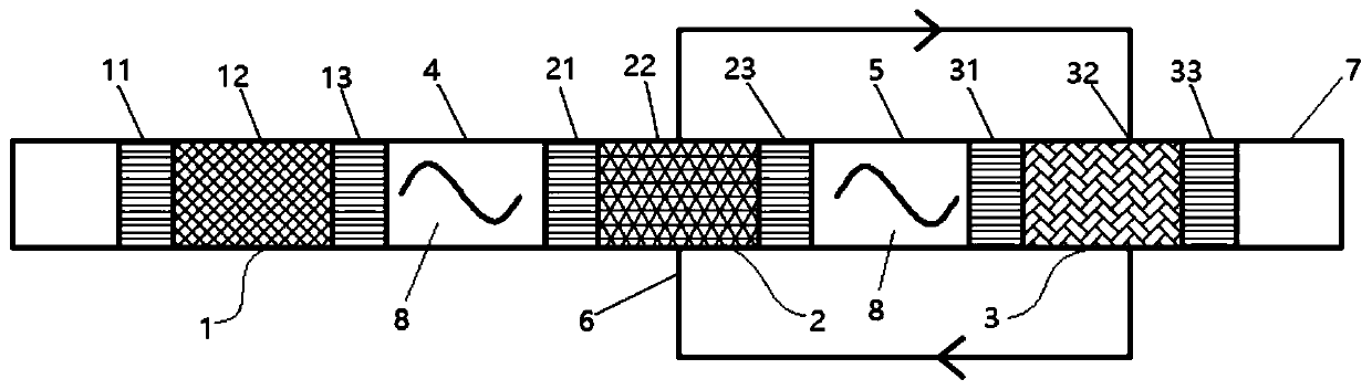
[0036] like figure 1 As shown, the thermoacoustic and electric card coupled refrigeration system driven by thermal energy provided by the embodiment of the present invention includes a thermoacoustic engine 1, a pyroelectric generator 2 and an electric card refrigerator 3, and the thermoacoustic engine 1 and the pyroelectric generator 2 is provided with a first heat buffer pipeline 4, and a second heat buffer pipeline 5 is provided between the pyroelectric generator 2 and the electric card refrigerator 3, and the pyroelectric generator 2 and the electric card refrigerator 3 are connected through wires 6 connections form a loop.

[0037] In the thermoacoustic and electric card coupled refrigeration system driven by thermal energy in the embodiment of the present invention, the thermoacoustic engine can convert heat into mechanical energy in the form of sound work to realize the conversion process of thermal work, and the fluid working medium in the thermoacoustic engine driving...

Embodiment 2

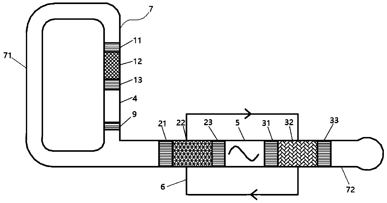
[0045] like figure 2 As shown, the refrigeration system of the second embodiment of the present invention is basically the same as that of the first embodiment above, the difference is that the pipe body 7 includes an annular pipe 71 and a resonant pipe 72, the resonant pipe 72 communicates with the annular pipe 71, and the thermoacoustic engine 1 is set In the annular tube 71 , the pyroelectric generator 2 and the electric card refrigerator 3 are arranged in the resonant tube 72 . In this embodiment, the tube body is divided into two parts, the annular tube and the resonance tube. The thermoacoustic engine is independently arranged in the ring tube, and the pyroelectric generator and the electric card refrigerator are sequentially arranged in the resonance tube along the extension direction of the resonance tube. The position of the person can be changed. Since the ring tube is in communication with the resonance tube, part of the sound work generated by the thermoacoustic ...

Embodiment 3

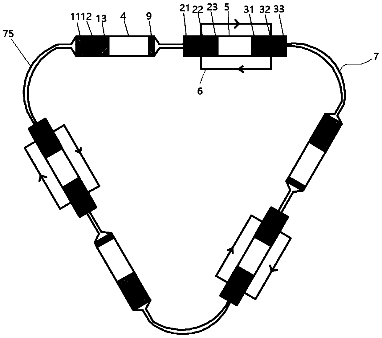
[0048] like image 3 As shown, the third embodiment of the present invention is basically the same as the refrigeration system of the second embodiment above. The group is arranged in the annular pipe 75, and the pyroelectric generator 2 and the electric card refrigerator 3 are arranged between two adjacent thermoacoustic engines 1 . In this embodiment, a thermoacoustic engine, a pyroelectric generator, an electric card refrigerator and a secondary heat exchanger form a refrigeration unit, and the three refrigeration units are arranged sequentially in the annular pipe, thus forming a loop type multiple Level thermal energy drives the pyroelectric-electric card refrigeration system.


PUM


Abstract

The invention relates to the technical field of refrigeration, in particular to a thermo-acoustic and electro-caloric coupling refrigeration system driven by thermal energy. The system comprises a thermo-acoustic engine, a pyroelectric engine and an electro-caloric refrigerating machine, wherein a first thermal buffer pipeline is arranged between the thermo-acoustic engine and the pyroelectric engine; a second thermal buffer pipeline is arranged between the pyroelectric engine and the electro-caloric refrigerating machine; and in addition, the electro-caloric refrigerating machine and the pyroelectric engine are connected through a conductor to form a loop. By use of the thermo-acoustic and electro-caloric coupling refrigeration system, the problems in a traditional gas compression refrigeration technology that movement parts and systems are large and complex and refrigerating fluids are harmful to an environment can be solved, the thermo-acoustic engine is combined with the pyroelectric engine and the electro-caloric refrigerating machine, the characteristics that the thermo-acoustic engine has a wide working frequency rang, is completely free from no movement components and can drive a working medium to carry out reciprocating motion can be used for replacing a traditional mechanical pump, the system is free from motion abrasion, is noiseless and is safe and reliable, meanwhile, the stability of the system is improved, and the system is compact.

Description

technical field [0001] The invention relates to the technical field of refrigeration, in particular to a thermoacoustic and electric card coupled refrigeration system driven by thermal energy. Background technique [0002] The traditional vapor compression refrigeration system is composed of four main parts: compressor, condenser, throttling device, and evaporator. In the refrigeration system, it circulates in a fluid state, and through phase change, it continuously absorbs heat from the evaporator and releases heat in the condenser, so as to achieve the purpose of refrigeration. Although this technology is relatively mature, there are problems such as large and complex systems, refrigerants that are harmful to the environment, and moving parts in the refrigeration system are prone to wear and damage. [0003] Electric card refrigeration uses the electric card effect of ferroelectric materials, that is, uses the effect of changes in adiabatic temperature or isothermal entro...

Claims


Application Information

Patent Timeline
Patent Type & Authority Applications(China)
IPC IPC(8): F25B21/00F25B49/00
CPCF25B21/00F25B49/00Y02B30/00
Inventor 罗二仓孙岩雷罗开琦胡剑英吴张华张丽敏陈燕燕喻绍飞
Owner TECHNICAL INST OF PHYSICS & CHEMISTRY - CHINESE ACAD OF SCI
Why Eureka
Try Eureka