Abnormality detection method, projection device, and computer-readable storage medium

A technology for abnormality detection and projection equipment, which is applied in the field of detection and can solve problems such as the inability to determine the heat dissipation of the light source in time, and the easy damage of the light source.

Active Publication Date: 2022-03-25
GOERTEK OPTICAL TECH CO LTD
View PDF0 Cites 0 Cited by
  • Summary
  • Abstract
  • Description
  • Claims
  • Application Information

AI Technical Summary

Problems solved by technology

[0003] The present invention provides an abnormality detection method, a projection device and a computer-readable storage medium, aiming to solve the problem in the prior art that the heat dissipation of the light source cannot be determined in time, resulting in the overheating and easy damage of the light source

Method used


Image

  • Abnormality detection method, projection device, and computer-readable storage medium
  • Abnormality detection method, projection device, and computer-readable storage medium
  • Abnormality detection method, projection device, and computer-readable storage medium

Examples


no. 1 example

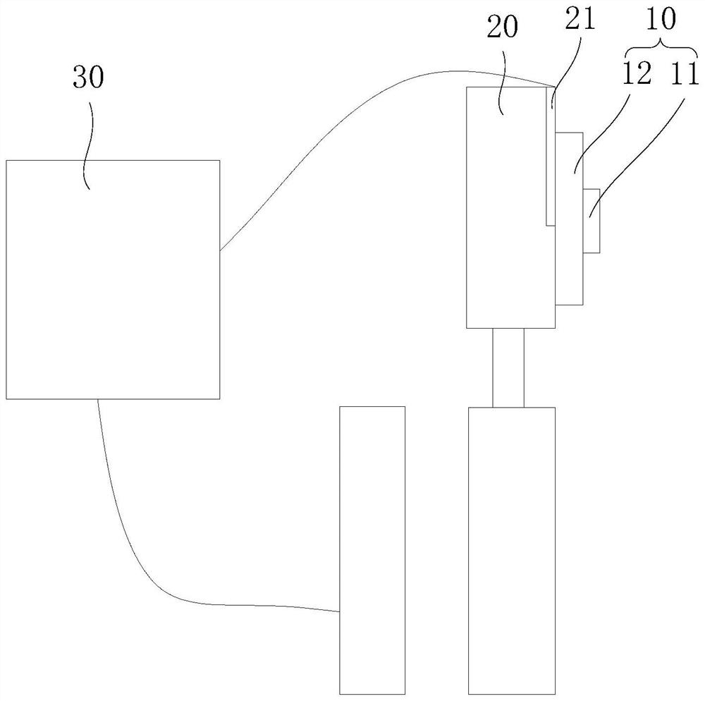
[0058] Please refer to figure 2 , the projection device includes a light source, a first temperature sensor and a heat sink, the light source includes a light source body and a light source substrate, the heat sink is arranged on a side of the light source substrate away from the light source body, the first A temperature sensor is used to measure the temperature of the heat sink, and the abnormal detection method includes:

[0059] S100, acquiring the temperature of the heat sink according to the first temperature sensor;

[0060] Wherein the first temperature sensor is used to detect the temperature on the heat sink, specifically, the first temperature sensor can be a contact temperature sensor or a non-contact temperature sensor, specifically, when the first temperature sensor is In the case of a contact temperature sensor, the first temperature sensor may be a thermocouple or a thermistor, and in the case of a non-contact temperature sensor, the first temperature sensor ...

no. 2 example

[0068] In the first embodiment, the S100 includes:

[0069] After the light source is started, the step of acquiring the temperature of the heat sink detected by the first temperature sensor is performed.

[0070] Wherein, when the light source is in a non-working state, the light source does not generate heat, so there is no need to measure the temperature of the heat sink, and when the light source is activated, the projection device receives the light source from the light source start message, so as to start to obtain the temperature of the heat sink of the heat sink through the first temperature sensor.

no. 3 example

[0072] In the first embodiment, the reference temperature is a preset temperature, specifically, the preset temperature refers to a temperature curve or a temperature value pre-stored by the projection device for detecting the abnormal state.

[0073] When the preset temperature is a temperature change curve within a certain time range, the projection device compares with the temperature change curve according to the temperature change of the heat sink, and obtains the heat dissipation at different times The difference between the temperature of the sheet and the temperature change curve.

[0074] When the maximum value of the difference is greater than the preset difference, it means that the light source is in an abnormal state of heat dissipation; when the maximum value of the difference is smaller than the preset difference, it means that the light source is in an abnormal state of heat dissipation state.


PUM


Abstract

The invention discloses an abnormality detection method, a projection device and a computer-readable storage medium. The abnormality detection method is applied to a projection device. The projection device includes a light source, a first temperature sensor, and a heat sink. The light source includes a light source body and a The light source substrate, the heat sink is arranged on the side of the light source substrate away from the light source body, the first temperature sensor is used to measure the temperature of the heat sink, and the abnormality detection method includes: according to the first A temperature sensor acquires the temperature of the heat sink; determines the difference between the temperature of the heat sink and a reference temperature; when the difference is greater than or equal to a preset difference, it is determined that the heat dissipation of the light source is abnormal. The invention provides an abnormality detection method, a projection device and a computer-readable storage medium, which solves the problem in the prior art that the heat dissipation of the light source cannot be determined in time, resulting in the overheating and easy damage of the light source.

Description

technical field [0001] The invention relates to the technical field of detection, in particular to an abnormality detection method, a projection device and a computer-readable storage medium. Background technique [0002] The light source is one of the important components of the projection equipment. The quality of the light source directly affects the imaging quality of the projection equipment. During the working process of the light source, the temperature of the light source will gradually increase with the increase of working time, and the temperature of the light source will affect the The light intensity and imaging effect of the light source have a great influence. Usually, after the light source substrate carrying the light source is connected to the heat sink, the heat sink is used to dissipate heat from the light source, so that the working temperature of the light source can be changed within a certain range. When assembling the light source and the heat sink, t...

Claims


Application Information

Patent Timeline
Patent Type & Authority Patents(China)
IPC IPC(8): G01M11/00G01K13/00G01J5/00
CPCG01M11/00G01K13/00G01J5/00
Inventor 高文刚
Owner GOERTEK OPTICAL TECH CO LTD
Why Eureka
Try Eureka