
Method and system for monitoring and recording switch life of switch module

A switch module and switch life technology, applied in the field of switch module switch life monitoring and recording method and system, can solve problems such as inability to warn and prompt, inability to view the number of times of switch on and off in real time, etc., and achieve the effect of accurate statistics

Inactive Publication Date: 2020-01-17
CHINA ELECTRONIS TECH INSTR CO LTD
View PDF6 Cites 1 Cited by
  • Summary
  • Abstract
  • Description
  • Claims
  • Application Information

AI Technical Summary

Problems solved by technology

[0006] In order to solve the above problems, the present invention proposes a switch module switch life monitoring and recording method and system, which can solve the problems that the above-mentioned traditional switch modules cannot check the number of on-off times of each switch in real time and cannot give early warning prompts

Method used


Image

  • Method and system for monitoring and recording switch life of switch module
  • Method and system for monitoring and recording switch life of switch module

Examples


Embodiment 1

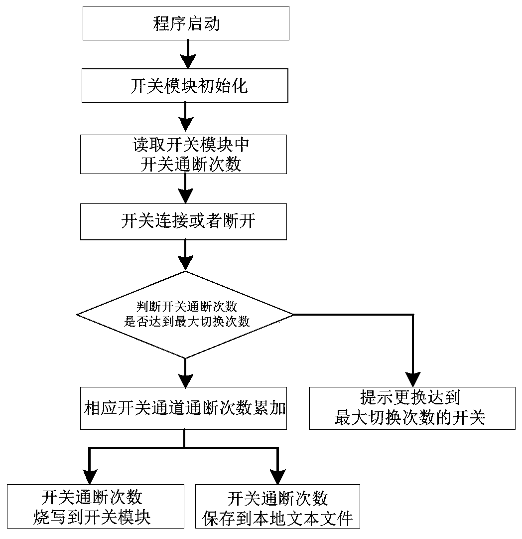
[0035] In one or more embodiments, a switch module switch life monitoring and recording method and system are disclosed, refer to figure 1 , including the following steps:

[0036] (1) Real-time acquisition of the switch on-off times stored in the switch module;

[0037] (2) Every time the switch module performs a switch, it will judge whether the number of switching times of the switch exceeds the maximum number of switching times.

[0038] (2.1) If the number of switch on and off exceeds the maximum number of switching times, it is prompted to replace the switch that has reached the maximum number of switching times. If the number of switching channels does not exceed the maximum number of switching times, the number of on-off times of the corresponding switching channel is accumulated once.

[0039] (2.2) Through the switch module, the on-off times of each switch can be viewed in real time; when the switch module is reset or closed, if there is a switch in the connected s...

Embodiment 2

[0045] In one or more embodiments, a switch module switch life monitoring and recording system is disclosed, including:

[0046] A module for obtaining the number of switch on-off times saved in the switch module in real time;

[0047] A module that is used to accumulate the number of on-off times of the switch channel every time the switch module switches the switch state;

[0048] A module for automatically judging whether the switching times of the switch channel exceed the maximum switching times;

[0049] A module for automatic alarm prompts when the maximum number of switching times is exceeded;

[0050] A module for programming the switch on-off times to the switch module in real time;

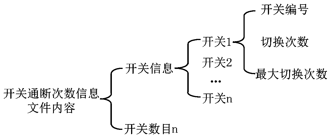
[0051] A module for automatically updating the local switch on-off times information file.

[0052] In some other embodiments, a switch module is disclosed, which adopts the switch module switch life monitoring and recording method described in Embodiment 1 to monitor the switch life...

Embodiment 3

[0054] In one or more embodiments, a terminal device is disclosed, including a server, the server includes a memory, a processor, and a computer program stored on the memory and operable on the processor, and the processor executes the The program implements the switch module switch life monitoring and recording method in the first embodiment. For the sake of brevity, details are not repeated here.


PUM


Abstract

The invention discloses a method and a system for monitoring and recording the switch life of a switch module. The method comprises the following steps of: acquiring switch on-off times stored in a switch module in real time; performing switch state switching every time by the switch module, wherein the on-off frequency of the switch channel is accumulated once, and whether the on-off frequency ofthe switch channel exceeds the maximum switching frequency or not is automatically determined; if yes, automatically giving an alarm prompt; otherwise, programming the on-off times of the switch intothe switch module; and updating a locally stored switch on-off frequency information file. The beneficial effects of the method and the system for monitoring and recording the switch life of the switch module are that the real-time recording and storage of the switching frequency of each switch are achieved, alarm prompt is given if the maximum switching frequency is reached to bring convenienceto a user for mastering the general use condition of the switch module.

Description

technical field [0001] The invention relates to the technical field of automatic testing of switch modules, in particular to a method and system for monitoring and recording the switch life of a switch module. Background technique [0002] The statements in this section merely provide background information related to the present invention and do not necessarily constitute prior art. [0003] The PXI bus switch module is the center of information exchange between the PXI bus automatic test system and the DUT. The PXI bus matrix switch module plays an important role in the automatic test system, and is widely used in the weapon equipment test system. In the automatic test system, the switch module plays the role of connecting the excitation instrument, the response instrument, and the tested part, and acts as the automatic link for the test. It establishes a channel for the test. [0004] The relays in the switch have a certain service life, that is, the maximum number of s...

Claims


Application Information

Patent Timeline
Patent Type & Authority Applications(China)
IPC IPC(8): G01R31/327
CPCG01R31/327
Inventor 曹光磊曹宁刘军智李龙
Owner CHINA ELECTRONIS TECH INSTR CO LTD
Learn More