Concealed resource prediction method and rock electromagnetic logging system
A resource prediction and electromagnetic technology, applied in electromagnetic wave detection, water resource assessment, and electrical/magnetic detection for logging records, etc., can solve the problems of single output parameter, shallow penetration depth, and narrow frequency range.
- Summary
- Abstract
- Description
- Claims
- Application Information
AI Technical Summary
Problems solved by technology
Method used
Image

Examples
Embodiment 1
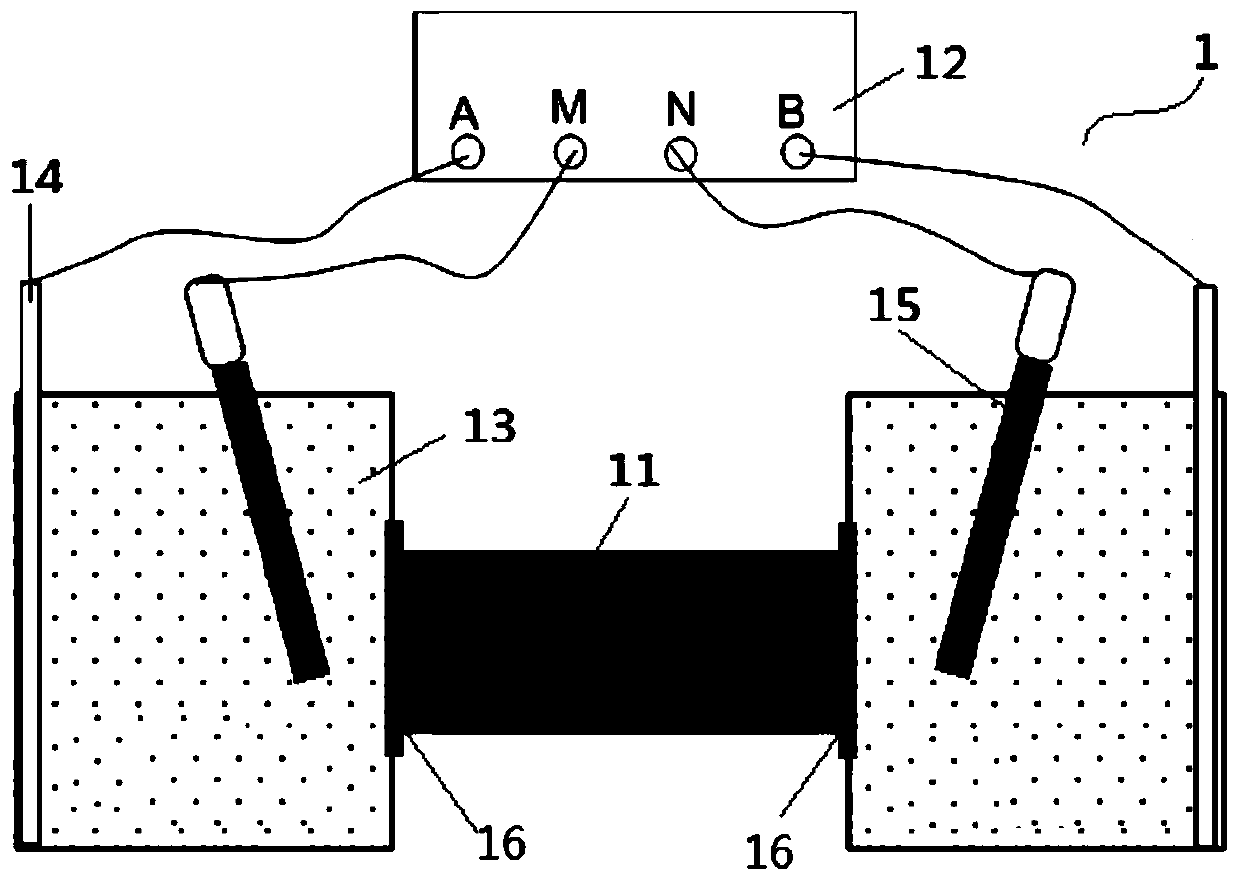
[0047] The rock electromagnetics measurement system 1 based on the core complex impedance measurement provided in this embodiment, such as figure 1 As shown, it includes two containers containing copper sulfate colloid 13 and an impedance analyzer 12, and the rock core sample 11 is placed between the two containers. Copper sulfate colloid is obtained by mixing about 1L saturated copper sulfate solution and about 5Kg flour (clay can also be used instead). A through hole is opened at the position where the outer wall of the container is in contact with the rock core sample 11, and a conductive glue 16 is arranged between the position where the rock core sample is in contact with the copper sulfate colloid. The transmitting ports A and B of the impedance analyzer 12 are respectively connected with the copper plate 14 inserted into the copper sulfate colloid 13 through wires, and the receiving ports M and N of the impedance analyzer are respectively connected with the reference el...
Embodiment 2
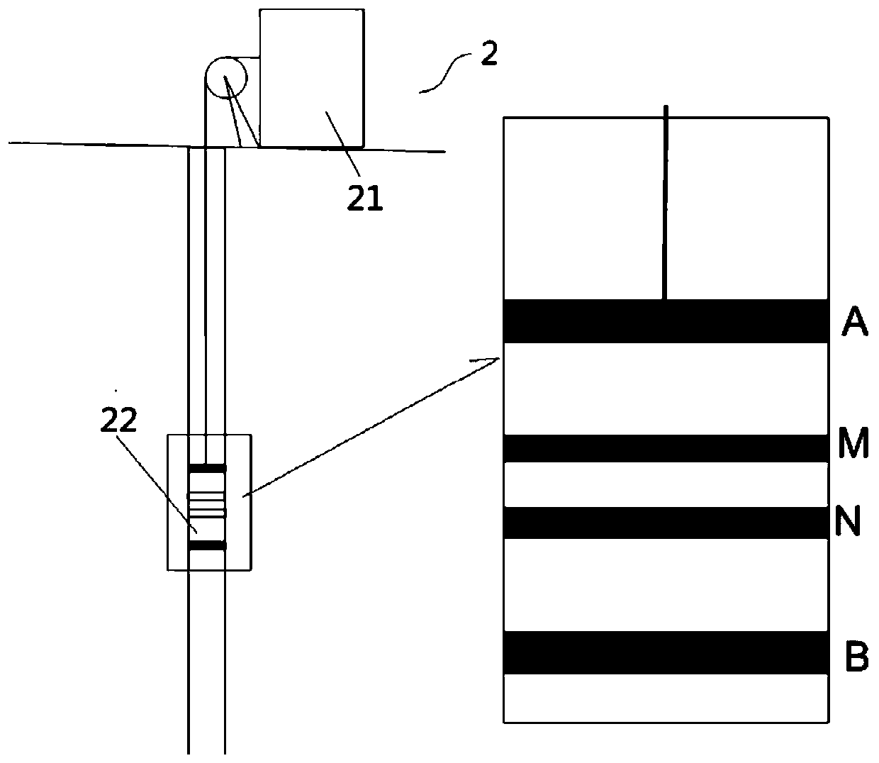
[0050] The rock electromagnetics logging system a2 based on the logging technology provided in this embodiment, such as figure 2 As shown, it includes a transmitting and receiving device 21 placed on the ground and an electrode device 22 placed in the logging; the electrode device includes transmitting electrodes (A, B) and receiving electrodes (M, N), and the transmitting electrodes (A, B) The transmitting end of the transmitting and receiving device is connected through the transmission line, and the receiving electrodes (M, N) are connected with the receiving end of the signal transmitting and receiving device through the transmission line. The transmitting part of the transmitting and receiving device is used to transmit electromagnetic waves with a frequency range of 0.001 to 10000 Hz. A signal generator or other devices with electromagnetic wave transmitting functions can be used to transmit broadband electromagnetic wave signals with different set frequencies undergroun...
Embodiment 3
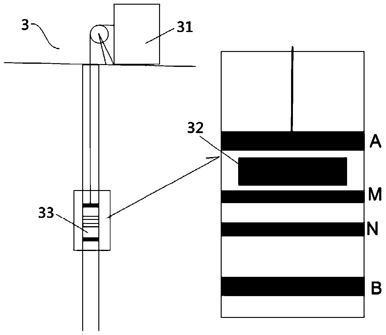
[0052] The rock electromagnetic logging system b3 based on logging technology provided by this embodiment, such as image 3 As shown, it includes a transmitting device 31 placed on the ground, a receiving device 32 and an electrode device 33 placed in the well logging, and the receiving device and the electrode device can be nested and installed together. The transmitting device is used to transmit electromagnetic waves with a frequency range of 0.001 to 10000 Hz. A signal generator or other devices with electromagnetic wave transmitting functions can be used to transmit broadband electromagnetic wave signals with different set frequencies underground and record the emission current. The receiving device can use a downhole electromagnetic receiver or a submarine electromagnetic receiver (the principle is the same as that of the ground electromagnetic receiver, but the volume can be as small as 15cm*5cm*5cm or even smaller) to record the AC voltage by measuring the receiving ele...
PUM
 Abstract
Description
Claims
Application Information
 - R&D
- Intellectual Property
- Life Sciences
- Materials
- Tech Scout
- Unparalleled Data Quality
- Higher Quality Content
- 60% Fewer Hallucinations
Browse by: Latest US Patents, China's latest patents, Technical Efficacy Thesaurus, Application Domain, Technology Topic, Popular Technical Reports.
© 2025 PatSnap. All rights reserved.Legal|Privacy policy|Modern Slavery Act Transparency Statement|Sitemap|About US| Contact US: help@patsnap.com