An automatic pressure relief high-voltage power distribution cabinet

A high-voltage power distribution cabinet and automatic venting technology, applied in the substation/distribution device casing, electrical components, substation/switch layout details, etc., can solve the problems of slow gas, difficult to discharge, affecting the turnover of the top plate, etc., to increase the service life , facilitate timely maintenance and increase the effect of usability

Active Publication Date: 2020-11-10
安徽卓越电力设备有限公司
View PDF16 Cites 0 Cited by
  • Summary
  • Abstract
  • Description
  • Claims
  • Application Information

AI Technical Summary

Problems solved by technology

[0003] In the prior art, the conventional pressure relief device is mostly a rectangular metal top plate, one side is fixed with iron screws, and the other side is fixed with nylon screws. When a fault occurs in the cabinet, the top plate deforms and opens to release pressure and discharge gas. After the pressure is released, the top plate is scrapped, and the use effect is not ideal. There is another way of pressure relief device: install a hinge on one side of the top plate, and fix the other side with nylon screws. When the pressure is released, the top plate is completely opened like a door, and the pressure relief channel is large. , but it will not damage the top plate, but it is easy to rebound and reclose after the top plate is turned over, making it difficult to discharge the subsequent slow gas. The complete turnover of the top plate will affect the turnover of the top plate of the adjacent power distribution cabinet, and the use effect is not ideal

Method used


Image

  • An automatic pressure relief high-voltage power distribution cabinet
  • An automatic pressure relief high-voltage power distribution cabinet
  • An automatic pressure relief high-voltage power distribution cabinet

Examples


Embodiment Construction

[0022] The following will clearly and completely describe the technical solutions in the embodiments of the present invention with reference to the accompanying drawings in the embodiments of the present invention. Obviously, the described embodiments are only some, not all, embodiments of the present invention. Based on the embodiments of the present invention, all other embodiments obtained by persons of ordinary skill in the art without making creative efforts belong to the protection scope of the present invention.

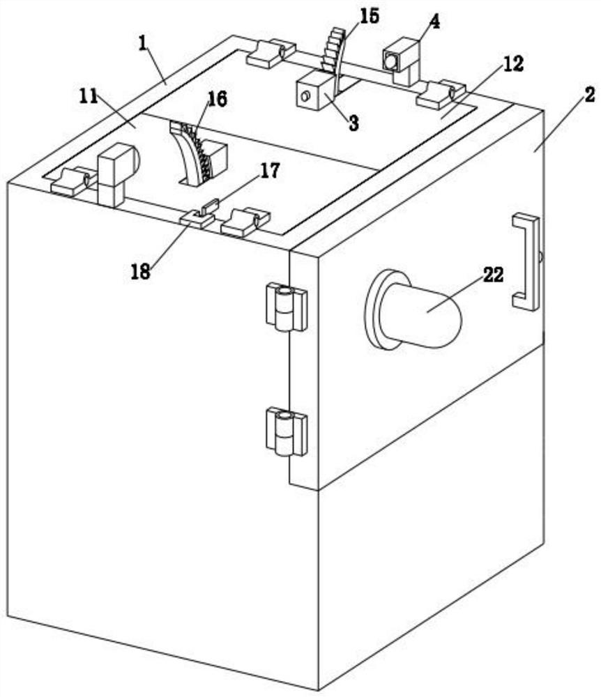
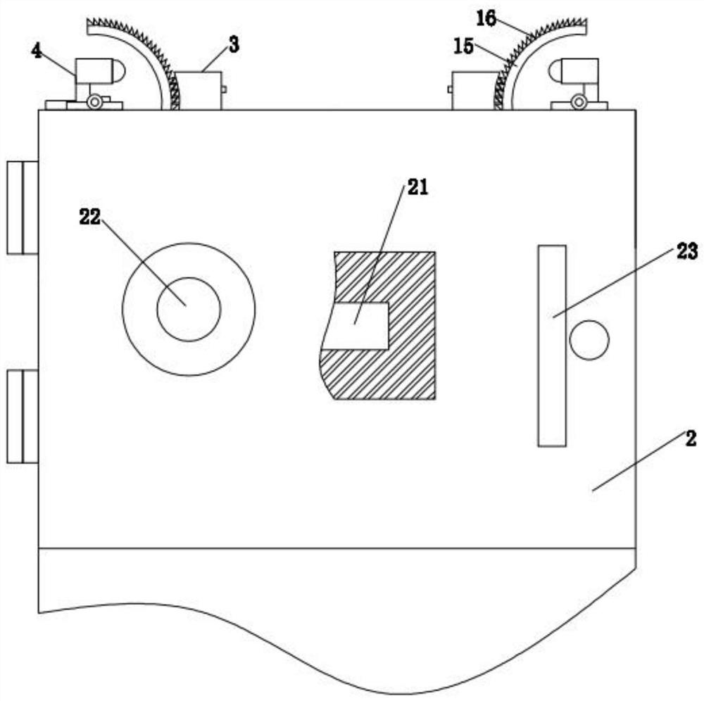
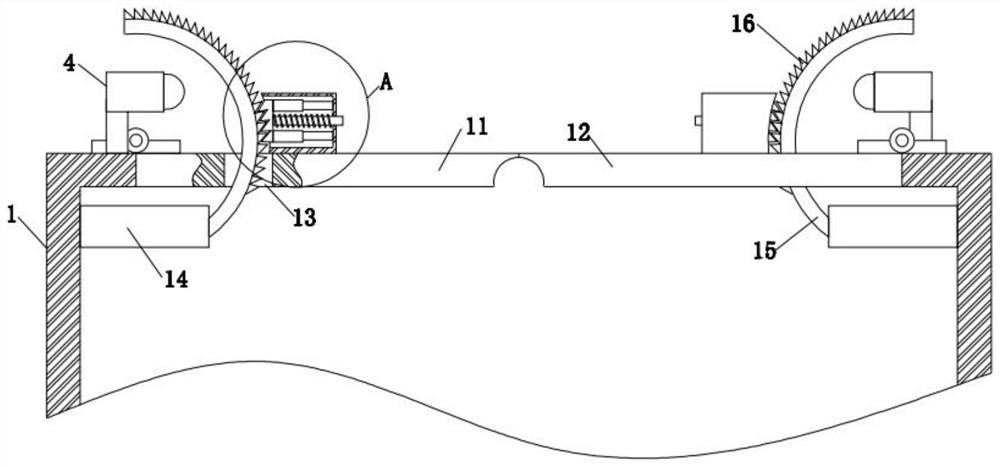
[0023] see Figure 1-5 , an automatic pressure relief high-voltage power distribution cabinet, including a cabinet body 1, a cabinet door 2, a buckle device 3 and a buffer device 4, the front of the cabinet body 1 is hinged with a cabinet door 2, and the upper surface of the cabinet body 1 A buckle device 3 and a buffer device 4 are fixedly installed, and the cabinet body 1 includes a first cover plate 11, a second cover plate 12, a movable hole 13, a fixed pl...


PUM


Abstract

The invention discloses an automatic pressure relief high-voltage power distribution cabinet, and relates to the technical field of power distribution cabinets. The cabinet comprises a cabinet body, acabinet door, a buckling device and a buffering device, the cabinet door is hinged to the front face of the cabinet body, the buckling device and the buffering device are fixedly installed on the upper surface of the cabinet body, and the cabinet body comprises a first cover plate, a second cover plate, a movable hole, a fixed plate, an arc-shaped plate, first clamping teeth, a connecting plate and a photoelectric sensor. By arranging the first cover plate, the second cover plate, the arc-shaped plate and the buckling device, the high-pressure gas enables the second clamping teeth and the first clamping teeth to be reversely meshed, so that the first cover plate and the second cover plate stably turn over; the purpose of releasing high-pressure and high-temperature gas is achieved; the first cover plate and the second cover plate are stably fixed to the surface of the arc-shaped plate through forward meshing of the second clamping teeth and the first clamping teeth, the situation thatsubsequent slow high-heat gas blocking occurs is avoided, the problem that a conventional pressure relief top plate is prone to springback and reclosing after being turned over is solved, and the usability of the device is improved.

Description

technical field [0001] The invention relates to the technical field of power distribution cabinets, in particular to an automatic pressure relief high-voltage power distribution cabinet. Background technique [0002] High-voltage distribution cabinets refer to electrical products that are used for on-off, control or protection in power system power generation, transmission, distribution, power conversion and consumption, and the voltage level is 3.6kV ~ 550kV. An important part of the electrical equipment manufacturing industry. During the operation of the high-voltage power distribution cabinet, a circuit short circuit fault occurs due to short circuit, insulation aging and human error, which will generate high temperature and high pressure gas. If it cannot be released in a short time, it will cause power distribution. Therefore, the top of the power distribution cabinet is usually equipped with a pressure relief device, but the existing pressure relief device still has th...

Claims


Application Information

Patent Timeline
Patent Type & Authority Patents(China)
IPC IPC(8): H02B1/30H02B1/38H02B1/54H02B13/025
CPCH02B1/30H02B1/38H02B1/54H02B13/025
Inventor 赵剑平汪传志王孝林
Owner 安徽卓越电力设备有限公司
Why Eureka
Try Eureka