Lubricating oil circulating type coupled disperser

A lubricating oil, circulating technology, applied in mixers, mixers with rotary stirring devices, fluid mixers, etc., can solve problems such as low mixing efficiency, achieve low cost, easy popularization and use, and occupy space. small effect

Inactive Publication Date: 2020-01-21
郝秀娥
View PDF9 Cites 1 Cited by
  • Summary
  • Abstract
  • Description
  • Claims
  • Application Information

AI Technical Summary

Problems solved by technology

However, this equipment cannot achieve repeated cycle stirring under the premise of small footprint, and the stirring efficiency is low

Method used


Image

  • Lubricating oil circulating type coupled disperser
  • Lubricating oil circulating type coupled disperser
  • Lubricating oil circulating type coupled disperser

Examples


specific Embodiment approach 1

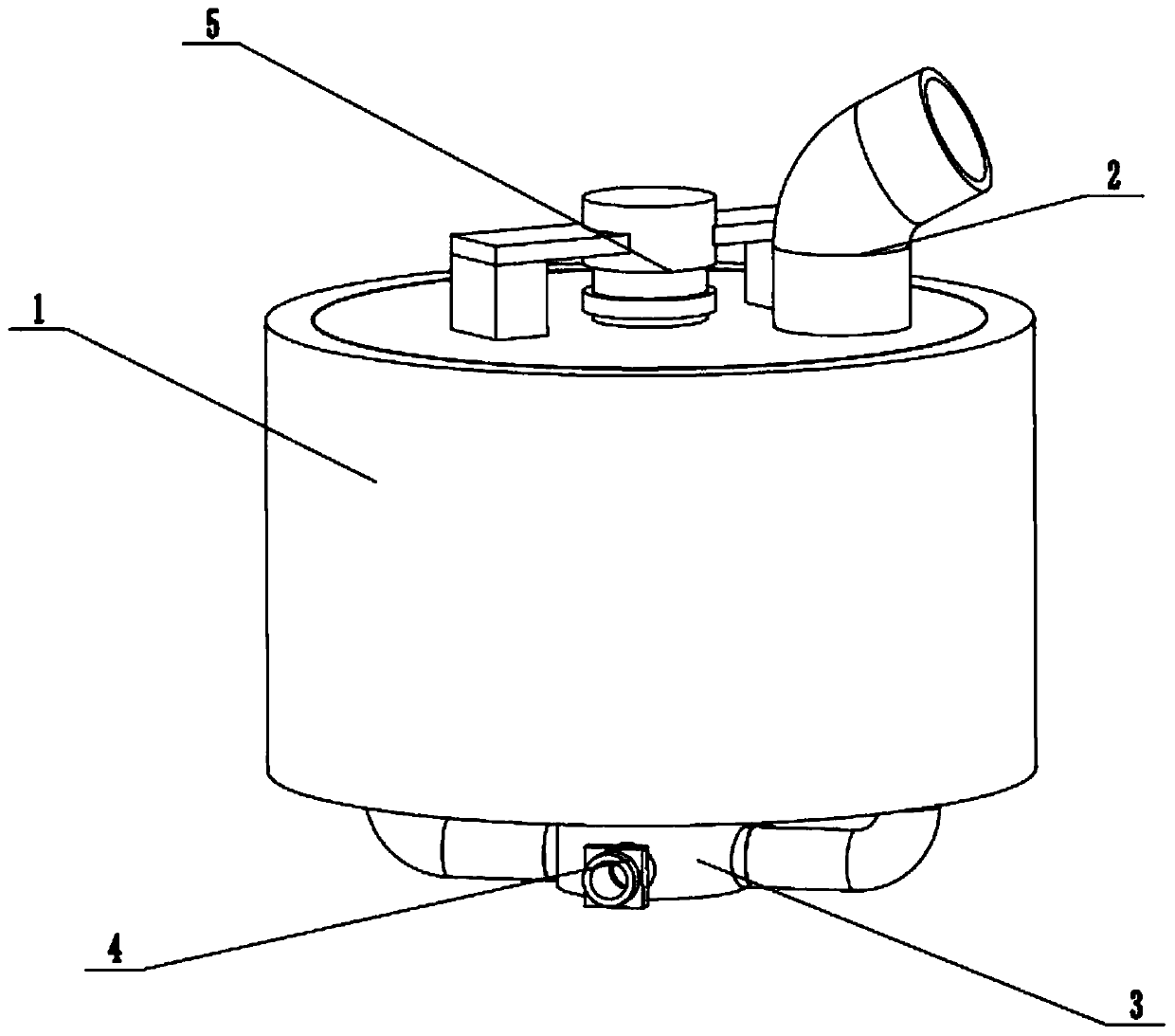
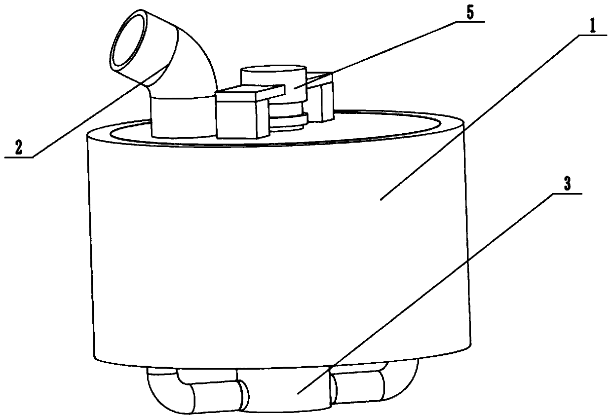
[0030] Such as Figure 1 to Figure 9 As shown, a lubricating oil circulating coupling disperser includes a lubricating oil dispersion box 1, an oil inlet pipe 2, a circulation box 3, a recovery pipe 4 with a valve, a dispersion driver 5 and a circulation driver 6, and the oil inlet pipe 2 is fixedly connected and connected to the eccentric position of the upper end of the lubricating oil dispersion box 1, the middle end of the circulation box 3 is fixedly connected to the center of the lower end of the lubricating oil dispersion box 1, and the circulation box 3 is connected to the lubricating oil dispersion box 1, with The recovery pipe 4 of the valve is fixedly connected and connected to the lower side of the rear end of the circulation box 3, the upper end of the dispersing driver 5 is fixedly connected to the upper end of the lubricating oil dispersing box 1, and the dispersing driver 5 is rotatably connected in the lubricating oil dispersing box 1, The circulation driver 6...

specific Embodiment approach 2

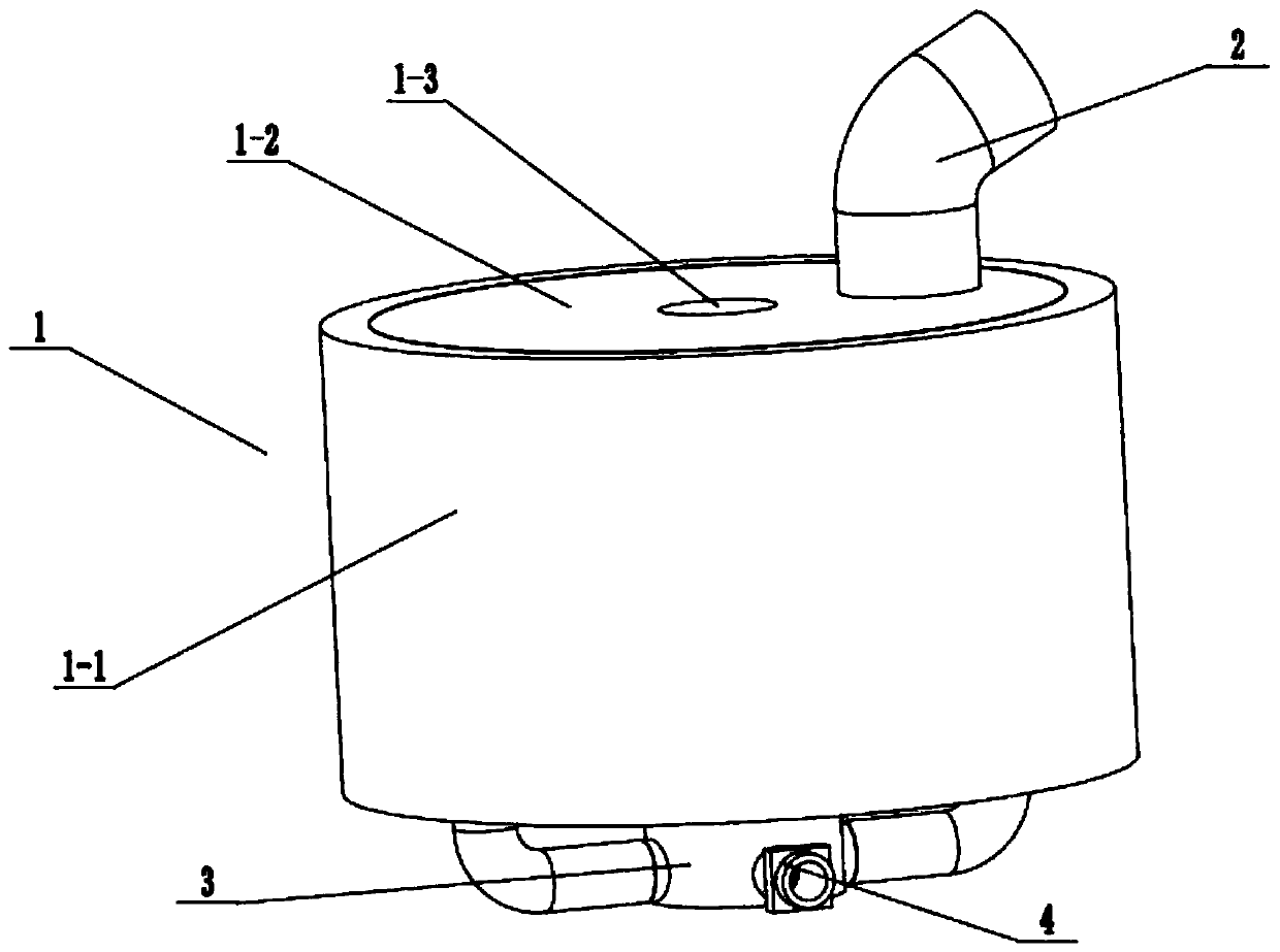
[0032] Such as Figure 1 to Figure 9As shown, this embodiment will further describe Embodiment 1. The lubricating oil distribution box 1 includes a main box 1-1, an upper end cover 1-2, an upper center turning hole 1-3 and a central partition ramp 1- 4. The upper end cover 1-2 is fixedly connected to the upper end of the inner wall of the main box body 1-1, and the eccentric part of the upper end cover 1-2 is provided with an opening, and the upper center turning hole 1-3 is set through the center of the upper end cover 1-2. The central partition ramp 1-4 is fixedly connected to the center of the inner wall of the main box body 1-1;

[0033] Described central separation slope plate 1-4 is provided with two circulating flow holes 1-5, four stirring shaft turning holes 1-6, four falling flowing holes 1-7 and lower center turning holes 1-8, two A circulation flow hole 1-5 is evenly arranged on the eccentric part of the central separation ramp 1-4, and four stirring shaft rotatio...

specific Embodiment approach 3

[0035] Such as Figure 1 to Figure 9 As shown, this embodiment further describes the second embodiment, the oil inlet pipe 2 is fixedly connected to the upper end of the upper end cover 1-2, and the oil inlet pipe 2 communicates with the opening of the upper end cover 1-2. The lubricating oil flows down to the central separation ramp 1-4 through the opening of the oil inlet pipe 2 and the upper end cover 1-2.


PUM


Abstract

The invention relates to the field of dispersing and stirring and particularly relates to a lubricating oil circulating type coupled disperser. The coupled disperser comprises a lubricating oil dispersing box body, an oil feeding pipe, a circulating box body, a recovery pipe with a valve, a dispersing driver and a circulating driver, wherein the oil feeding pipe is fixedly connected and communicated with the eccentric part of the upper end of the lubricating oil dispersing box body; the middle end of the circulating box body is fixedly connected to the center of the lower end of the lubricating oil dispersing box body; the circulating box body communicates with the lubricating oil dispersing box body; the recovery pipe with a valve is fixedly connected and communicated with the lower sideof the rear end of the circulating box body; the upper end of the dispersing driver is fixedly connected to the upper end of the lubricating oil dispersing box body. The coupled disperser has the beneficial effects that automatic stirring and circulation can be achieved, circulation stirring of lubricating oil is achieved, the phenomenon of uneven stirring or layered stirring of the lubricating oil in the use and transportation process is avoided, the stirring efficiency is high, the occupied space is small, the manufacturing cost is low, and application and popularization are facilitated.

Description

technical field [0001] The invention relates to the field of dispersing and stirring, in particular to a lubricating oil circulating coupling dispersing machine. Background technique [0002] The patent number is CN201510209602.2, which discloses a mobile disperser, which includes a material barrel and a cover matched with the material barrel. The cover is provided with a stirring shaft, and the stirring shaft is connected with a drive motor to drive its rotation. , also includes a lifting device for lifting the cover; the lifting device includes a drive mechanism, two or more transmission mechanisms for connecting the cover and the drive mechanism, and the transmission mechanism transfers the power of the drive mechanism transmission to the cover; the transmission mechanism is evenly distributed on the outer circumference of the material barrel; a bracket for installing the transmission mechanism is arranged outside the material barrel. In this invention, a lifting device ...

Claims


Application Information

Patent Timeline
Patent Type & Authority Applications(China)
IPC IPC(8): B01F7/16B01F5/10
CPCB01F25/52B01F27/85B01F2101/39
Inventor 郝秀娥
Owner 郝秀娥
Why Eureka
Try Eureka