Pathological slicing device
A technique of pathological slicing and slicing, which is applied in metal processing and other directions, can solve the problem of inability to slice pathological tissues continuously, achieve the effect of improving cutting effect and reducing time-consuming
- Summary
- Abstract
- Description
- Claims
- Application Information
AI Technical Summary
Problems solved by technology
Method used
Image
Examples
Embodiment 1
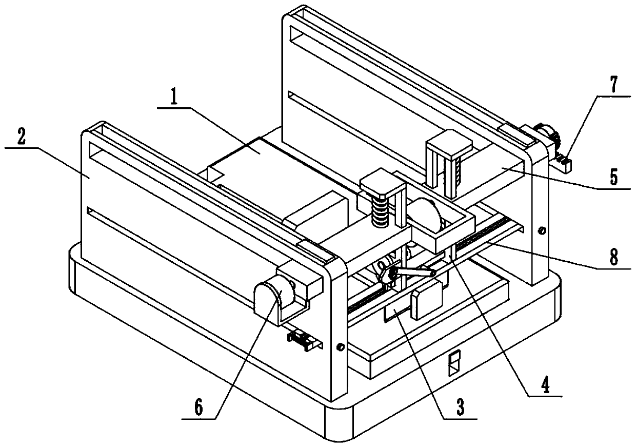
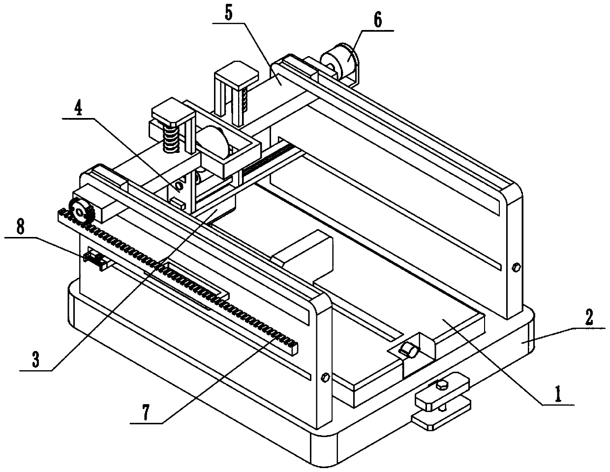
[0030] Such as Figure 1-10 As shown, a pathological slicing device includes a slicing platform 1, a complete machine support 2, a slice knife 3, a cutter seat 4, a sliding frame 5, a drive motor 6 and a straight rack 7, and the middle part of the complete machine support 2 is connected to There is a slicing platform 1; the slicing knife 3 is connected to the lower end of the cutter seat 4; the cutter seat 4 is connected to the sliding frame 5; the sliding frame 5 is slidably connected to the two ends of the whole machine support 2; The drive motor 6 is connected to the sliding frame 5 through the motor seat; the drive motor 6 is connected to the cutter seat 4 by transmission; the cutter seat 4 is connected to the spur rack 7 by transmission; the spur rack 7 is fixedly connected to the frame of the whole machine 2 on.
[0031] In a pathological slicing device of the present invention, when cutting a pathological tissue sample, after the pathological tissue sample is installed...
Embodiment 2
[0033] Such as Figure 1-10 As shown, the whole machine support 2 includes a base 201 and a side plate 202; two ends of the top surface of the base 201 are respectively fixedly connected to a side plate 202; the slicing platform 1 is connected to the base 201; the sliding frame 5 Slidingly connected to two side panels 202 .
Embodiment 3
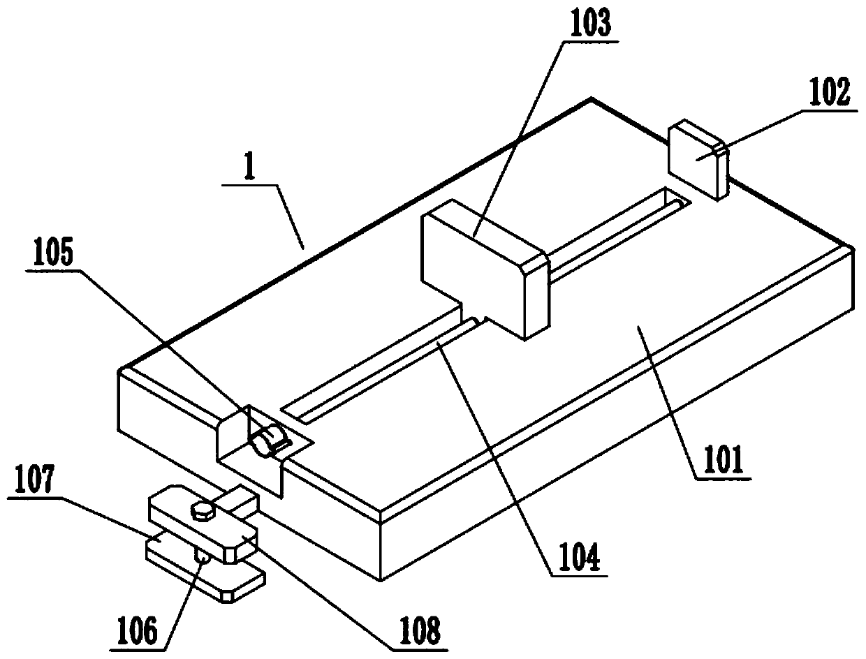
[0035] Such as Figure 1-10As shown, the slicing platform 1 includes a platform body 101, a fixed splint 102, a movable splint 103, a first screw 104, an adjustment rotary block 105, a second screw 106, a fixed plate 107 and a movable plate 108; the platform body 101 slides fit in the rectangular groove in the middle of the base 201; the fixed splint 102 is fixed on the front end of the top surface of the platform body 101; Connected to the first screw rod 104; the two ends of the first screw rod 104 are respectively rotated and matched with the two ends of the chute in the middle of the platform body 101; the rear end of the first screw rod 104 is fixedly connected to the adjusting block 105; The upper end of two screw rods 106 is threadedly connected on the movable plate 108; the rear end of the movable plate 108 is fixedly connected to the platform body 101; the lower end of the second screw rod 106 is rotatably fitted on the fixed plate 107; on the base 201. The slicing ...
PUM
 Abstract
Description
Claims
Application Information
 - R&D
- Intellectual Property
- Life Sciences
- Materials
- Tech Scout
- Unparalleled Data Quality
- Higher Quality Content
- 60% Fewer Hallucinations
Browse by: Latest US Patents, China's latest patents, Technical Efficacy Thesaurus, Application Domain, Technology Topic, Popular Technical Reports.
© 2025 PatSnap. All rights reserved.Legal|Privacy policy|Modern Slavery Act Transparency Statement|Sitemap|About US| Contact US: help@patsnap.com


