
Integrated label printing device

A label printing and equipment technology, applied in the direction of printing, printing machines, general parts of printing machinery, etc., can solve the problems of easy deviation of labels, label ink cannot be dried quickly, and low work efficiency, so as to achieve good drying effect, Prevent deviation and improve work efficiency

Active Publication Date: 2020-01-21
广东佳雅实业有限公司
View PDF5 Cites 3 Cited by
  • Summary
  • Abstract
  • Description
  • Claims
  • Application Information

AI Technical Summary

Problems solved by technology

[0002] A printing machine is a machine for printing text and images. A modern printing machine is generally composed of plate loading, ink application, embossing, paper feeding (including folding) and other mechanisms; label printing equipment is a type of printing machine; existing label printing equipment In the process of label transmission, the label is easy to deviate, and the ink on the surface of the label after printing cannot be dried quickly, and the work efficiency is low

Method used


Image

  • Integrated label printing device
  • Integrated label printing device
  • Integrated label printing device

Examples


Embodiment 1

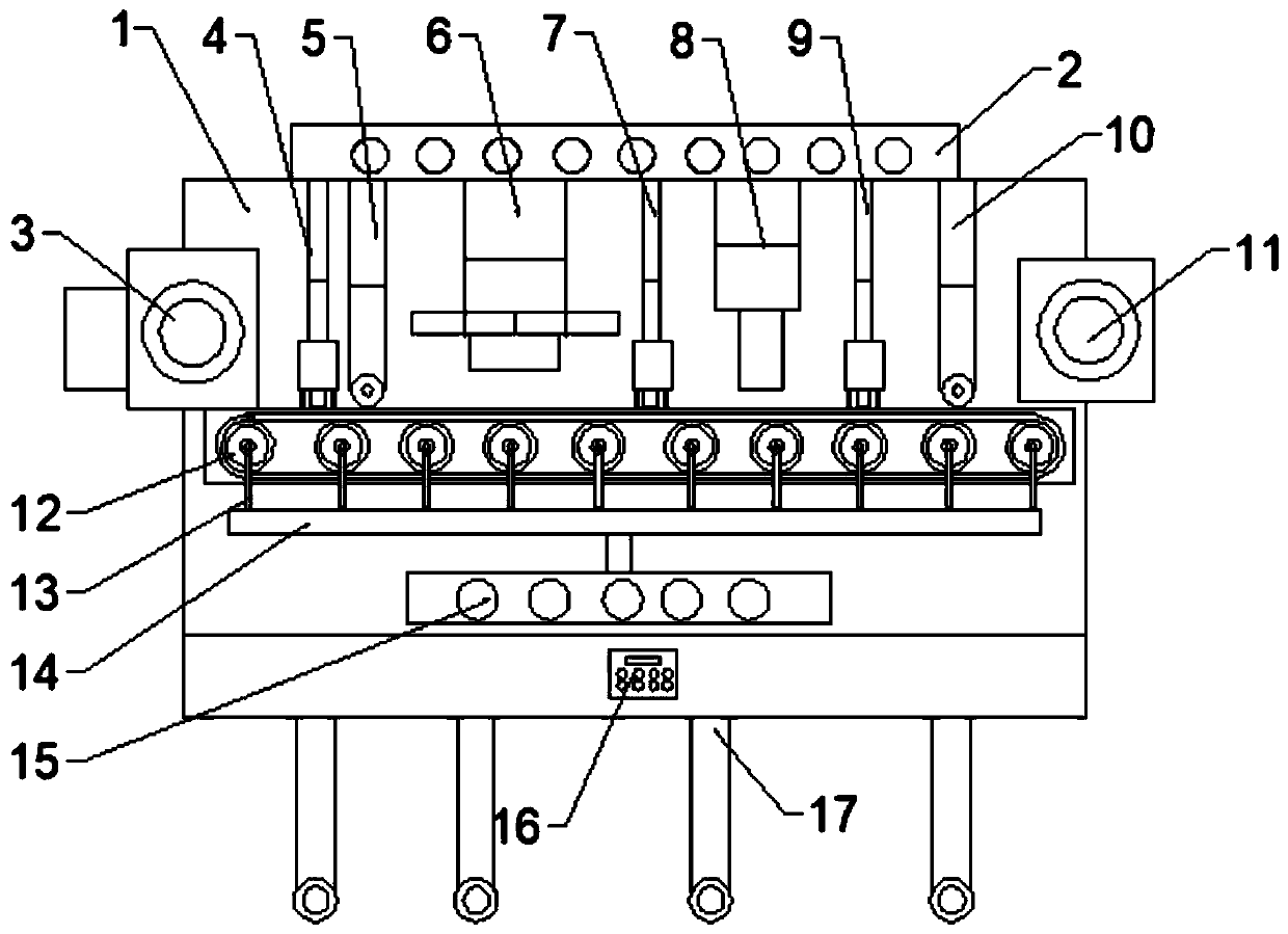
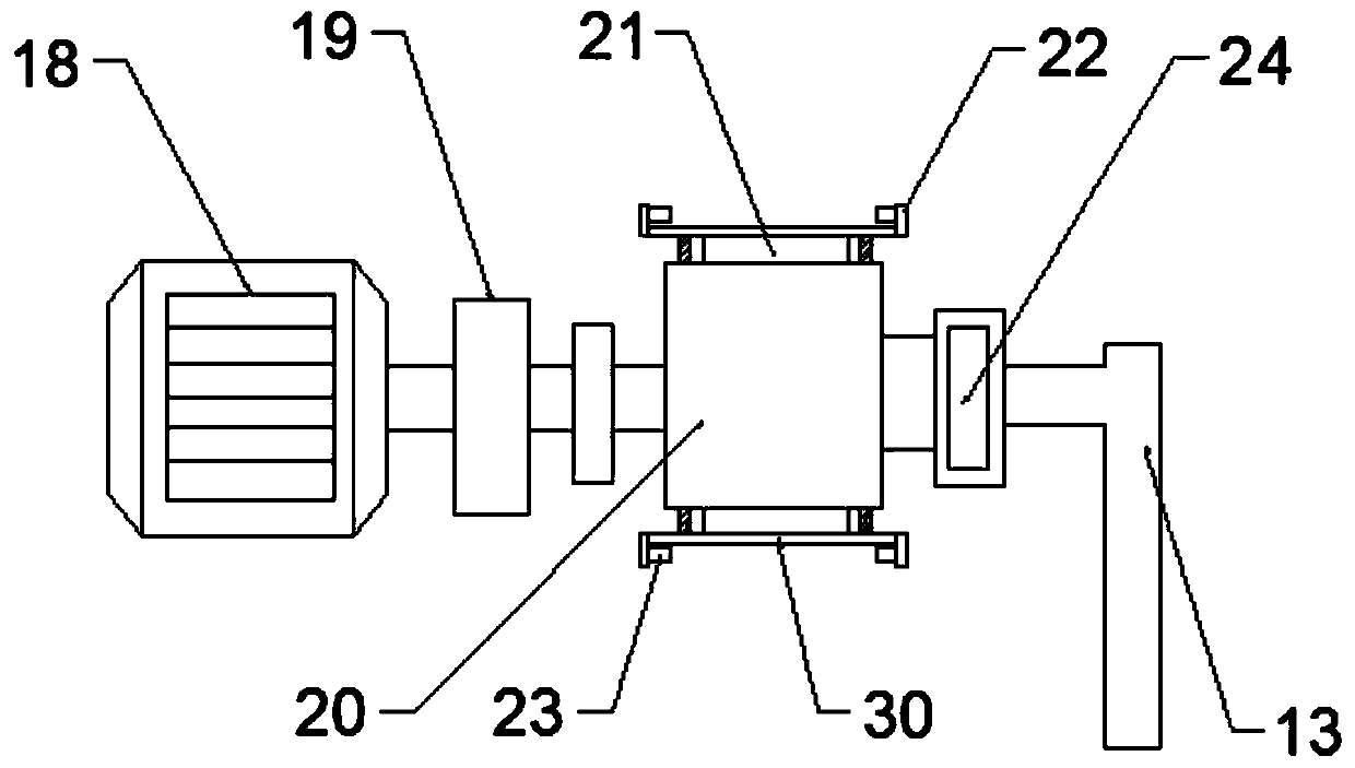
[0023] see Figure 1~3 , in the embodiment of the present invention, an integrated label printing equipment, including a body 1; a No. 1 hot air blower 2 is installed on the top of the body 1; an unwinding mechanism 3 is installed on the left side of the body 1; A winding mechanism 11 is installed on the side; No. 1 dryer 4, No. 1 guiding device 5, printing mechanism 6, No. 2 dryer 7, pressing mechanism 8, and three No. 9 dryer and No. 2 guide 10; the unwinding mechanism 3, printing mechanism 6, pressing mechanism 8 and winding mechanism 11 are prior art; the No. 1 dryer 4 and No. 1 guide 5. There is a transmission mechanism 12 under the printing mechanism 6, the No. 2 dryer 7, the pressing mechanism 8, the No. 3 dryer 9 and the No. 2 guide device 10; the No. 2 hot air blower is installed under the transmission mechanism 12 15; the body 1 is installed on the top of the base; a control panel 16 is installed on the base; a support rod 17 is installed at the bottom of the base. ...

Embodiment 2

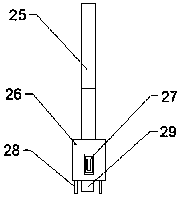
[0030] see figure 1 , the bottom end of the support rod 17 is connected to the universal wheel through the lifting device; the universal wheel can enter the inside of the support rod 17 through the lifting device.

[0031] The working principle of the present invention is: through the setting of several detection probes 28, reduce the moisture measurement error; through the setting of the air outlet 29, the ink on the upper part of the printed matter is dried; the hot air has a downward force on the printed matter, The probability of offset can be reduced; through the setting of the No. 2 dryer 7, the air distribution pipe 13, the clamping device 22, the drying roller 20 and the diffuser hole 21, the bottom of the printed matter is heated to improve the drying efficiency of the ink; through The setting of the clamping device 22 and the fixed block 23 can prevent the printed matter from deviating; the positioning before printing is carried out by the guide roller on the No. 1 g...


PUM


Abstract

The invention discloses an integrated label printing device. The integrated label printing device comprises a body, wherein a first air heater is mounted at the top end of the outer portion of the body; an unwinding mechanism is mounted on the left side of the body; a winding mechanism is mounted on the right side of the body; a first dryer, a first guiding device, a printing mechanism, a second dryer, a press-fit mechanism, a third dryer and a second guiding device are sequentially mounted at the top end of the inner portion of the body from left to right; a transmission mechanism is arrangedbelow the first dryer, the first guiding device, the printing mechanism, the second dryer, the press-fit mechanism, the third dryer and the second guiding device; a second air heater is mounted belowthe transmission mechanism; the body is mounted at the top of a base; a control panel is mounted on the base; and a supporting rod is mounted at the bottom end of the base. The integrated label printing equipment is good in drying effect, stable in operation and high in work efficiency.

Description

technical field [0001] The invention relates to the technical field of printing equipment, in particular to an integrated label printing equipment. Background technique [0002] A printing machine is a machine for printing text and images. A modern printing machine is generally composed of plate loading, ink application, embossing, paper feeding (including folding) and other mechanisms; label printing equipment is a type of printing machine; existing label printing equipment In the process of label transmission, the label is easy to deviate, and the ink on the surface of the label after printing cannot be dried quickly, and the work efficiency is low. [0003] Therefore, in view of the above status quo, it is urgent to develop an integrated label printing equipment with high work efficiency. Contents of the invention [0004] The object of the present invention is to provide an integrated label printing device to solve the problems raised in the above-mentioned background...

Claims


Application Information

Patent Timeline
Patent Type & Authority Applications(China)
IPC IPC(8): B41F23/04B65H16/00B65H18/08B65H23/038
CPCB41F23/0426B65H16/00B65H18/08B65H23/038
Inventor 刘倖呈刘永添肖国平
Owner 广东佳雅实业有限公司
Learn More