Magnetic speed reducing structure and sunshade curtain

A deceleration structure and sunshade technology, which is applied to building components, building structures, windows, etc., can solve problems such as curtain bumping, curtain shaking, and curtains occupying too much space, so as to prevent excessive unfolding and winding, and control the rotation of the shaft Speed, the effect of convenient shaft rotation speed

Pending Publication Date: 2020-01-21
董克思 +1
View PDF0 Cites 0 Cited by
  • Summary
  • Abstract
  • Description
  • Claims
  • Application Information

AI Technical Summary

Problems solved by technology

[0004] Due to the limited space in the car, excessive expansion of the curtains will cause the curtains to occupy too much space, causing inconvenience in use, and when the rotation speed of the rotating shaft is too fast, the speed of rolling and unfolding the curtains will also be too fast, which will cause problems in control. Inconvenience, and, when the drive shaft is stopped to rotate, the shaft is easy to keep rotating under the action of inertia and continue to rotate at a larger angle, so that the curtains are excessively rolled and unfolded
In the process of rolling up the curtain by the rotating shaft, if the rotating speed of the rotating shaft is too fast, the curtain will shake greatly, which will easily cause the curtain to collide with other objects, and will affect the service life
Therefore, there is a problem in the prior art that the rotation speed of the shaft of the sunshade is difficult to control.

Method used


Image

  • Magnetic speed reducing structure and sunshade curtain
  • Magnetic speed reducing structure and sunshade curtain
  • Magnetic speed reducing structure and sunshade curtain

Examples


Embodiment 1

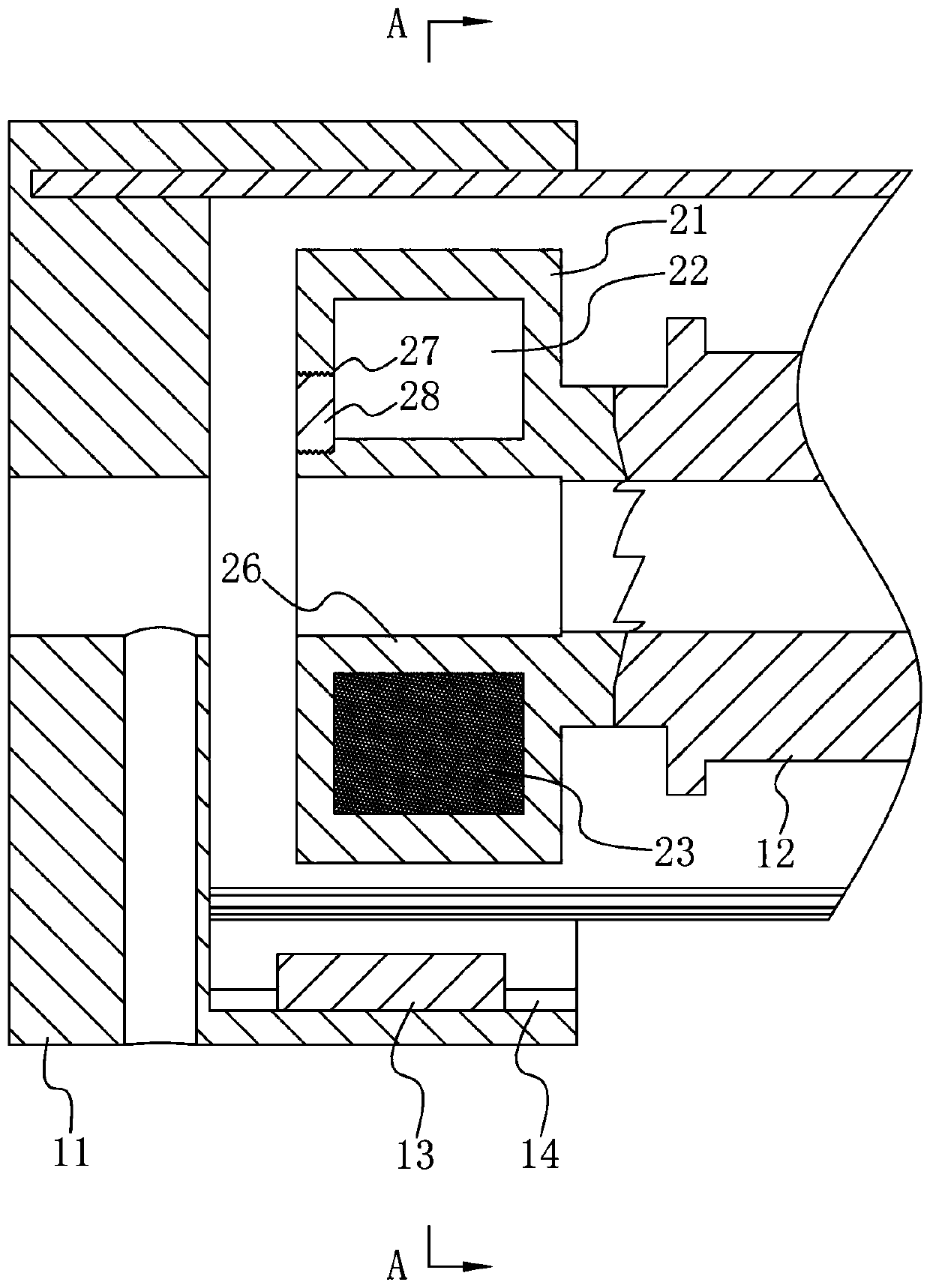
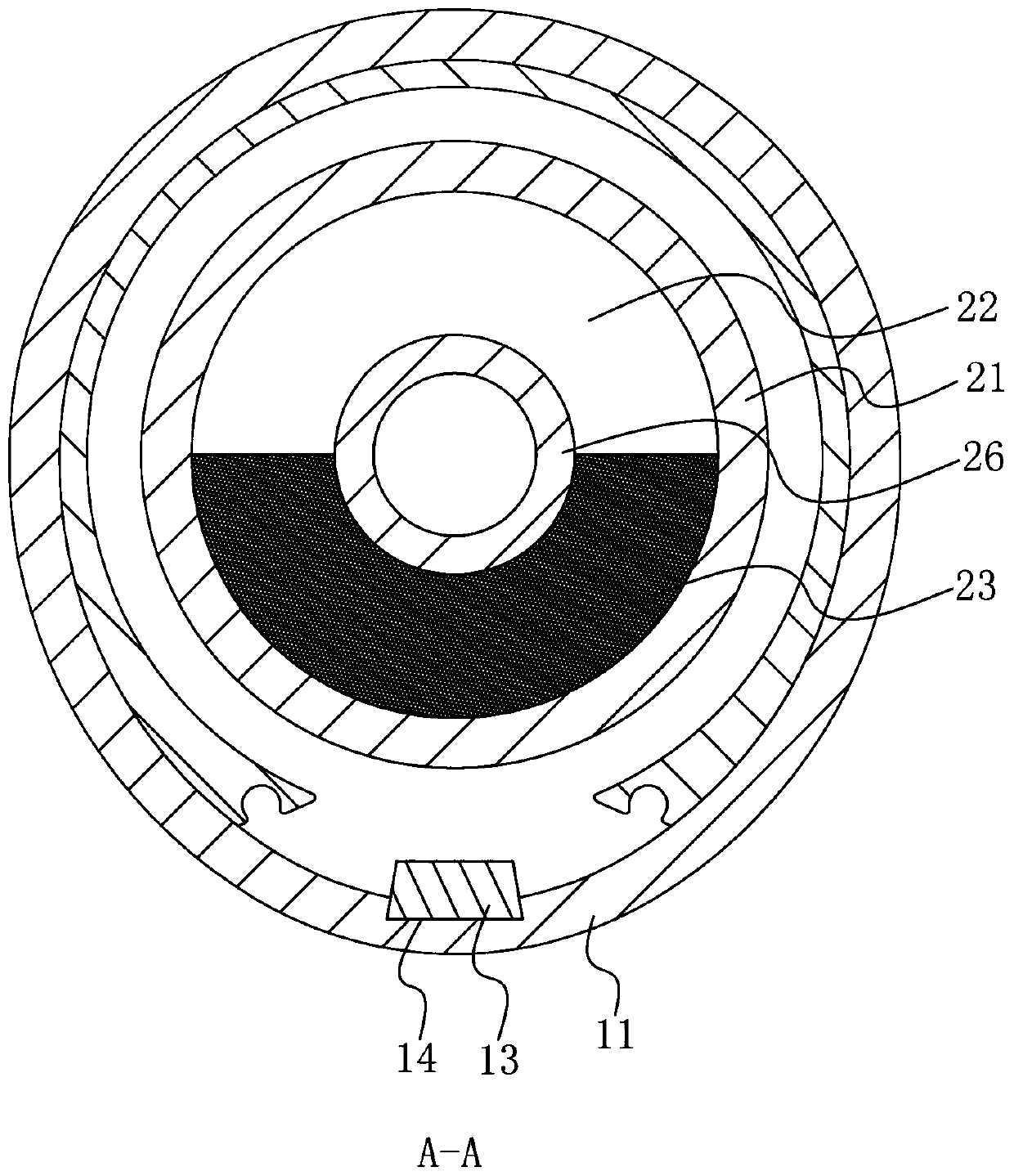
[0030] A magnetic deceleration structure such as figure 1 and figure 2 As shown, it includes a fixed housing 11, a rotating shaft connector 12, a magnetic member 13 and a reduction sleeve 21. The magnetic member 13 is a magnet. Part 12 is connected to the rotating shaft of the sunshade, and the reduction sleeve 21 is installed on the rotating shaft connector 12. The outer surface of the reduction sleeve 21 is generally cylindrical with the rotation center of the rotating shaft connector 12 as the axis, and the reduction sleeve 21 and the rotation shaft connector 12 The speed reduction sleeve 21 is provided with a housing chamber 22, and the housing chamber 22 is provided with a magnetic guide 23. Any cross section of the housing chamber 22 along the direction of the rotation axis of the shaft connector 12 is in the shape of the speed reduction sleeve 21 axis. The center is a circle with the center, and the magnetic part 13 is located on one side of the reduction sleeve 21 in...

Embodiment 2

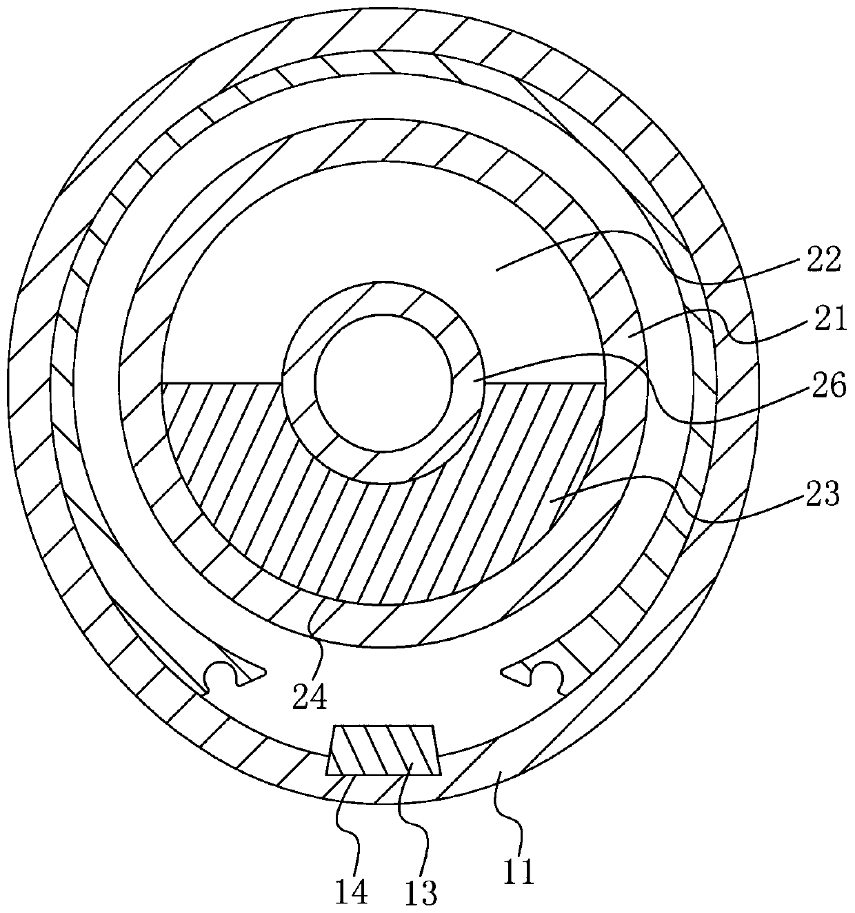
[0051] A magnetic deceleration structure such as image 3 As shown, the difference between it and Embodiment 1 is that the magnetically conductive part 23 is a discus, and the discus is provided with an arc-shaped surface 24 that fits the inner wall of the reduction sleeve 21 .

[0052] This embodiment has the following advantages:

[0053] Through the arrangement of the arc surface 24, the relative sliding between the discus and the reduction sleeve 21 is more stable, and the vibration and noise are reduced. Provide stable resistance to the rotating shaft, which is convenient to control the rotating speed of the rotating shaft.

Embodiment 3

[0055] A magnetic deceleration structure, which is different from Embodiment 1 in that: the magnetic conducting member 23 is an iron ball.

[0056] This embodiment has the following advantages:

[0057] During the rotation of the reduction sleeve 21, the iron balls can roll in the accommodation chamber 22, so that the friction between the magnetic guide 23 and the reduction sleeve 21 is transformed into rolling friction with less friction, so that the magnetic guide 23 is easier to Move in the direction close to the magnetic piece 13. Preventing the friction force between the magnetic conducting part 23 and the speed reduction sleeve 21 from being too large, causing the magnetic conduction part 23 to rotate circularly with the speed reduction sleeve 21, so as to improve reliability and stability. Provide stable resistance to the rotating shaft, which is convenient to control the rotating speed of the rotating shaft.


PUM


Abstract

The invention discloses a magnetic speed reducing structure, and relates to the technical field of sunshade curtains for vehicles. The problem that the rotating speed of a rotating shaft of the sunshade curtain is difficult to control is solved. The magnetic speed reducing structure is technically characterized by comprising a fixed shell, a rotating shaft connecting piece, a magnetic piece and aspeed reducing sleeve, the magnetic piece and the fixed shell are clamped in the rotating circumferential direction of the rotating shaft connecting piece, the outer surface of the whole speed reducing sleeve is in a cylindrical shape with the rotating center of the rotating shaft connecting piece as the axis, the speed reducing sleeve and the rotating shaft connecting piece are circumferentiallyclamped, a containing cavity is formed in the speed reducing sleeve, a magnetic conduction piece is arranged in the containing cavity, the arbitrary cross section in the rotating axial direction of the rotating shaft connecting piece of the containing cavity is in a circular shape with the axis of the speed reducing sleeve as the center, and the magnetic piece is located on the upward side of thespeed reducing sleeve. The invention further discloses a sunshade curtain which comprises a sunshade curtain body and the magnetic speed reducing structure. The sunshade curtain is simple in structure, stable and reliable and can keep providing resistance for the rotating of the rotating shaft and also reduce the influences of the abrasion to the speed reducing sleeve on the speed reducing effect.

Description

technical field [0001] The invention relates to the technical field of sunshade curtains for vehicles, in particular to a magnetic deceleration structure and a sunshade curtain. Background technique [0002] Automobiles are an important means of transportation for people to travel and provide convenience for people's travel. Because the car is outdoors most of the time, when the sun shines into the cabin through the car window, the interior of the car will become hot, and the strong light will also cause inconvenience to the driver's driving. [0003] In order to block the sunlight that irradiates into the cabin by the car window, people have made automobile sunshade roller blinds, and when not using the sunshade roller blinds, they rotate and roll up the curtains by rotating shafts. When the sun needs to be blocked, the curtain is pulled, and the curtain drives the rotating shaft to rotate, and the curtain is unrolled from the reel; when the sun does not need to be blocked...

Claims


Application Information

Patent Timeline
Patent Type & Authority Applications(China)
IPC IPC(8): B60J1/20E06B9/56
CPCB60J1/2036E06B9/56
Inventor 董克思李磊
Owner 董克思
Why Eureka
Try Eureka