Permeable Gravity Retaining Wall Structure Embedded with Crushed Stone Columns and Its Construction Method

A kind of retaining wall and gravity type technology, applied in the water permeable type gravity type retaining wall structure and its construction field, can solve the problems such as the inability to remove water in time, the inability to release seepage energy, and the easy occurrence of disasters, and achieve obvious social and economic benefits. Benefit, safe and reliable construction method, simple process effect

Active Publication Date: 2020-08-25
HEBEI UNIV OF TECH
View PDF2 Cites 0 Cited by
  • Summary
  • Abstract
  • Description
  • Claims
  • Application Information

AI Technical Summary

Problems solved by technology

The retaining wall is simple in construction and has good water permeability, but the structure has light weight and poor stability. In addition, during heavy rainfall, the soil behind the wall is accompanied by a large amount of rainwater, and it is very likely to slide rapidly. The groove behind the retaining wall may be in the Blockage state, unable to remove the water in the unstable soil in time
Invention patent CN109972653A discloses a permeable double-row retaining wall for urban buildings. The retaining wall is provided with drainage holes on the concrete base, and two rows of walls of unequal height are arranged on the upper part, which are connected by ribs to form a trapezoidal hollow body. The gravel backfill layer is laid on the gap. The structural performance of the retaining wall is good. However, in the case of heavy rainfall in mountainous areas, the seepage water of the hillside cannot be discharged through the retaining wall, and the seepage energy in the slope soil cannot be released, which is very easy. Disaster occurred

Method used


Image

  • Permeable Gravity Retaining Wall Structure Embedded with Crushed Stone Columns and Its Construction Method
  • Permeable Gravity Retaining Wall Structure Embedded with Crushed Stone Columns and Its Construction Method
  • Permeable Gravity Retaining Wall Structure Embedded with Crushed Stone Columns and Its Construction Method

Examples


Embodiment Construction

[0032] Hereinafter, preferred embodiments of the present invention will be described in detail with reference to the accompanying drawings. It should be understood that the preferred embodiments are only for illustrating the present invention, but not for limiting the protection scope of the present invention.

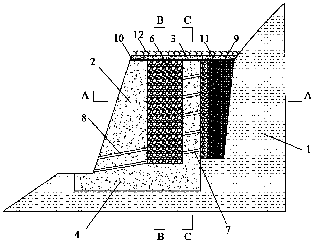
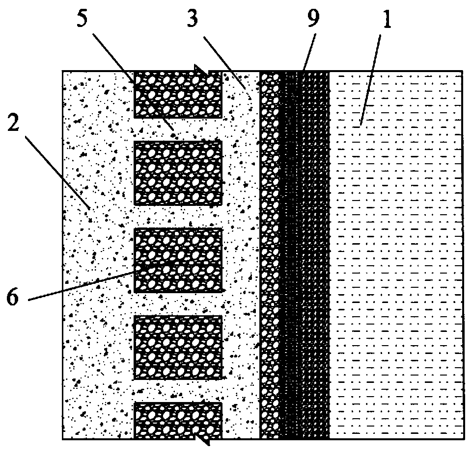
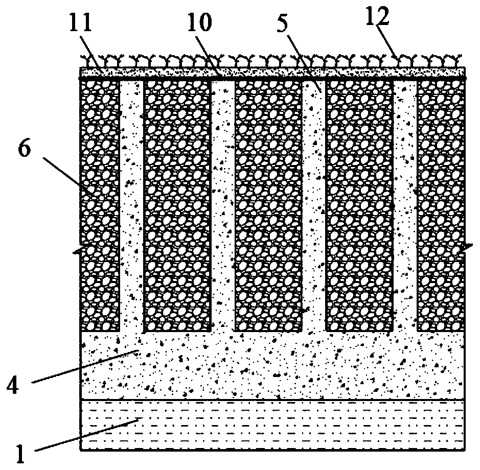
[0033] Such as figure 1 As shown, a permeable gravity retaining wall structure with embedded crushed stone columns includes a concrete wall, wherein the concrete wall is divided into a front wall 2, a rear wall 3, a longitudinal wall 5 and a base 4 The four parts, the front wall 2, the rear wall 3, the longitudinal wall 5 and the base 4 are cast in place as a whole; the front wall 2 and the rear wall are arranged at intervals A plurality of longitudinal walls are connected, and the front and rear walls, and the lower parts of the plurality of longitudinal walls are all fixed on the base 4; the space surrounded by the base, the front and rear walls, and the longitudina...


PUM


Abstract

The invention discloses a water-permeable gravity type retaining wall structure with embedded gravel columns and a constructing method of the retaining wall structure. The retaining wall structure comprises a concrete wall body. The concrete wall body comprises a front side wall, a rear side wall, longitudinal walls and a base which are integrated through pouring in a cast-in-place mode. The frontside wall and the rear side wall are connected through longitudinal walls at intervals. The space defined by the base, the front side wall, the rear side wall and the longitudinal walls is filled with the embedded gravel columns. The space between the concrete wall body and a side slope soil body is filled with graded sand filter bed filling earth. The front side wall and the rear side wall are each provided with a drainage channel. The drainage channels communicate with the embedded gravel columns and the graded sand filter bed filling earth. The concrete wall body and a behind-wall graded gravel layer form a drainage system, a large amount of water can be drained within a short period of time, the drainage decompression effect is realized, the side slope soil body is prevented from sliding, stability is high, and construction is convenient.

Description

technical field [0001] The invention relates to the technical field of slope support and slope drainage, in particular to a permeable gravity retaining wall structure embedded with gravel columns and a construction method thereof. Background technique [0002] In the mountainous area of ​​southwestern my country, the rainfall is very heavy, and landslides are extremely prone to occur. The gravity retaining wall maintains itself and the stability of the slope by the weight of the retaining wall. However, due to heavy rainfall, the water content of the slope increases, which can easily lead to the instability of the gravity retaining wall. Therefore, the permeable function of the gravity retaining wall Particularly important. Many retaining walls have drainage holes in the wall for drainage, but when encountering heavy rainfall, it is often difficult for the drainage holes in the wall to discharge a large amount of water in a short time, and because the rain is accompanied by...

Claims


Application Information

Patent Timeline
Patent Type & Authority Patents(China)
IPC IPC(8): E02D29/02
CPCE02D29/02E02D29/0275
Inventor 黄达杨芸芸钟助宋宜祥吴礼舟裴向军
Owner HEBEI UNIV OF TECH
Why Eureka
Try Eureka