Heat-insulation fireproof door and window system
A technology for doors, windows and heat insulation, applied in fire doors, door/window applications, windows/doors, etc., can solve the problems of high cost, cumbersome structure, inconvenient installation, etc., to improve the convenience of installation, reduce costs, The effect of depth size reduction
- Summary
- Abstract
- Description
- Claims
- Application Information
AI Technical Summary
Problems solved by technology
Method used
Image
Examples
Embodiment 1
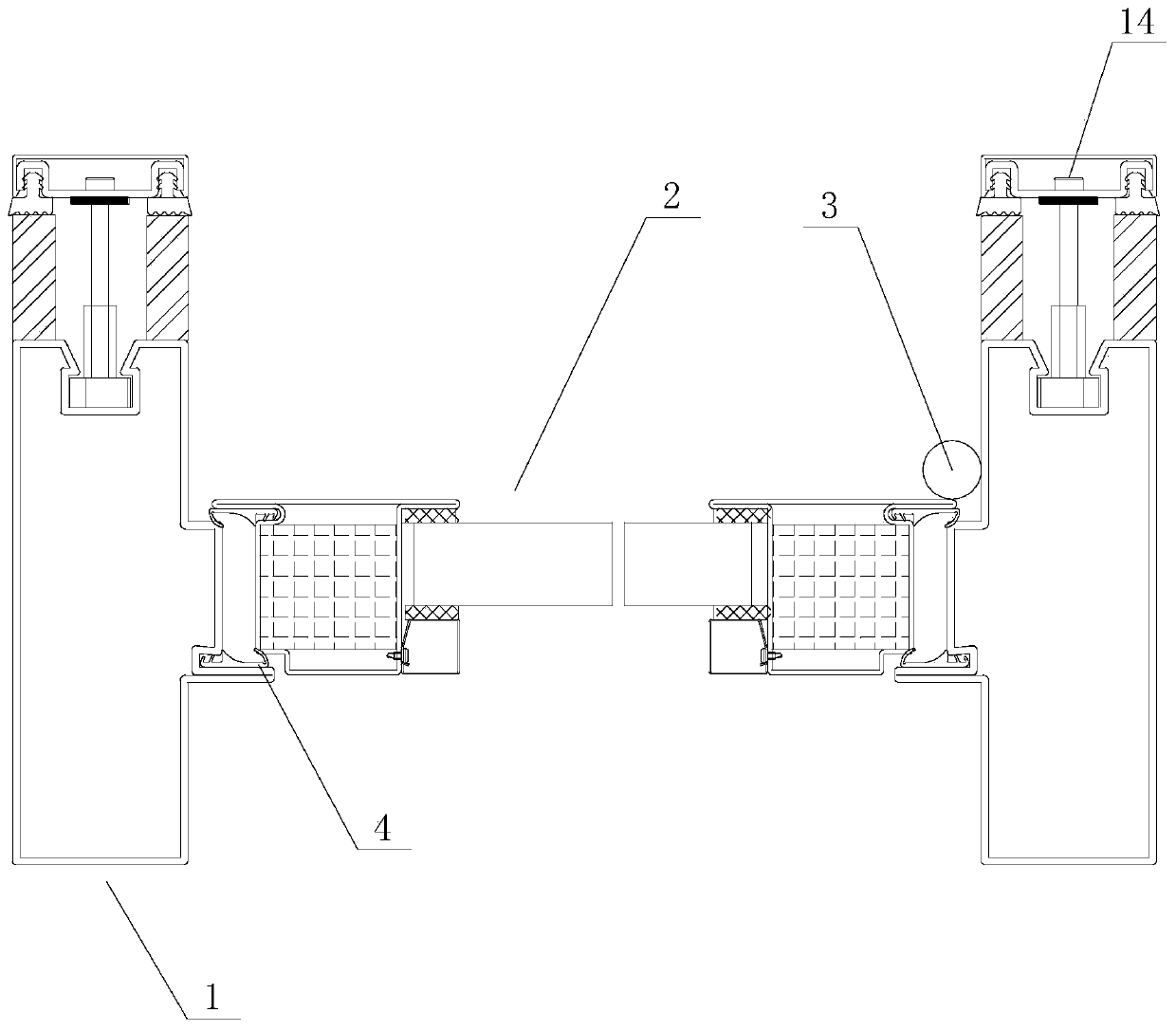
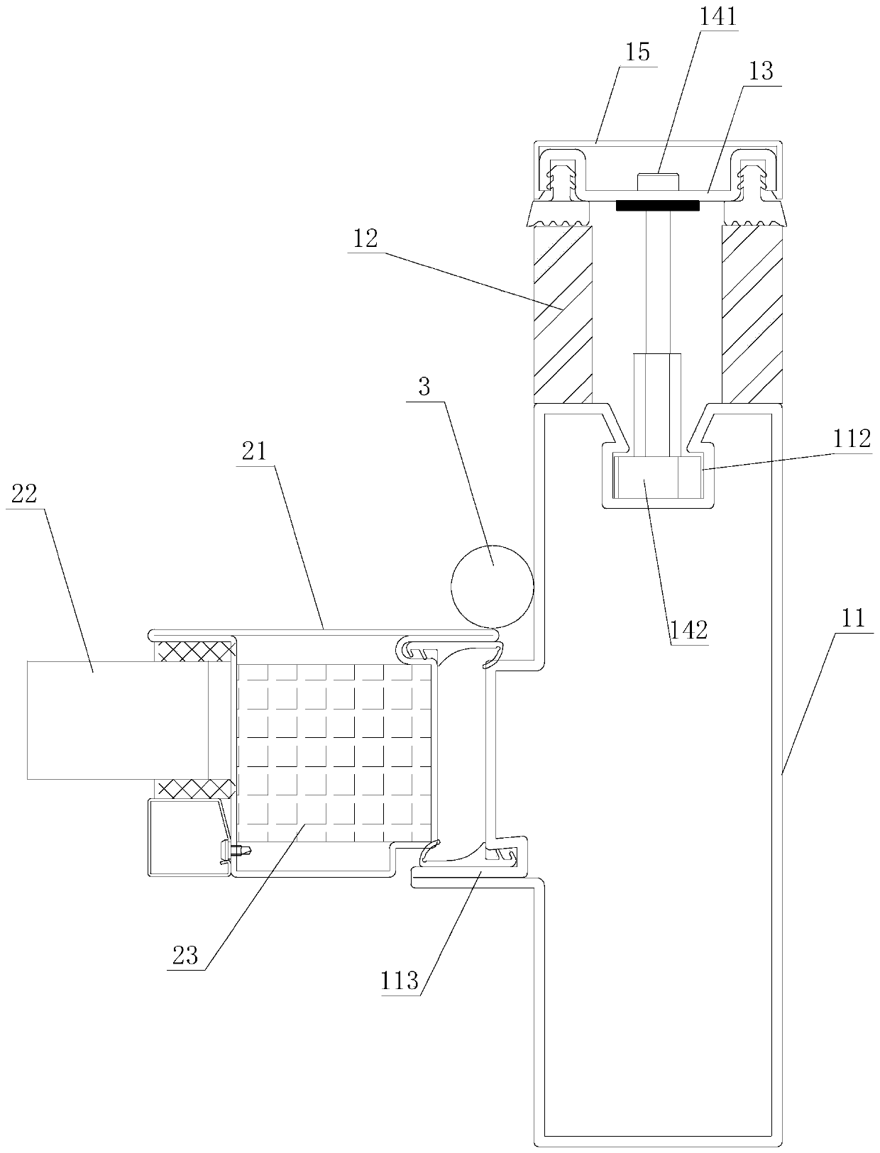
[0035] Such as figure 1 with figure 2 As shown, the first embodiment of the heat insulation and fireproof door and window system of the present invention includes a door frame 1 and an opening fan 2. The door frame 1 includes a steel frame 11, a heat insulating part 12, a pressing plate 13 and a locking part 14, and the heat insulating part 12 Set on at least one side of the steel frame 11 in the direction of the heat transfer path, the pressure plate 13 is pressed on the heat insulation 12, and the locking piece 14 connects the pressure plate 13 and the steel frame 11 and drives the pressure plate 13 to compress the heat insulation 12. One side of the opening fan 2 is hinged to the steel frame 11 through the hinge 3 . In this structure, the heat insulation position of the door frame 1 is set on the tube surface on one side of the steel frame 11 in the direction of the heat transfer path, and the heat insulation piece 12 is fastened on the tube surface through the pressure p...
Embodiment 2
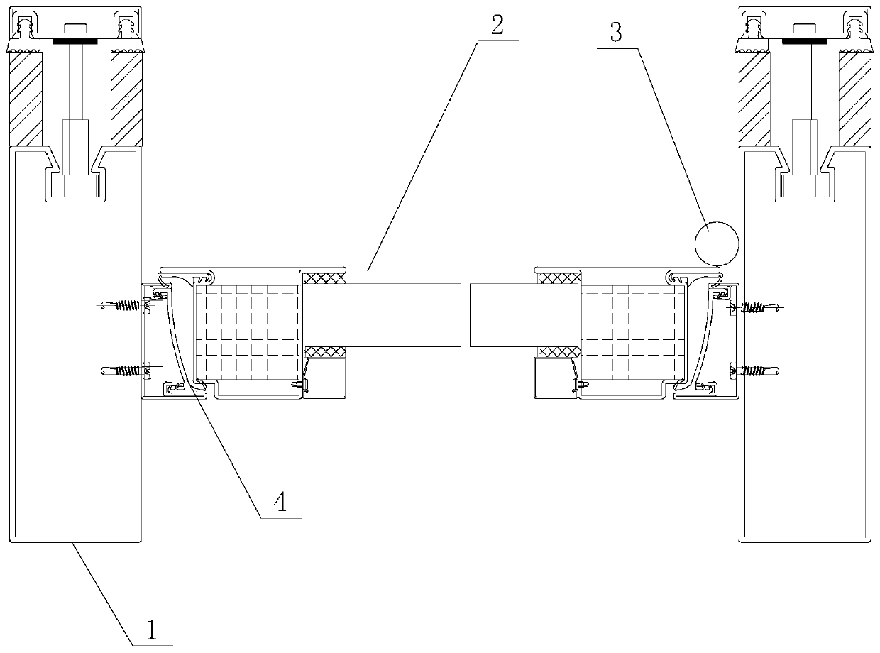
[0045] Such as image 3 with Figure 4 As shown, the second embodiment of the heat-insulating and fireproof door and window system of the present invention is basically the same as that of Embodiment 1, the only difference being that in this embodiment, the steel frame 11 is equipped with a limit auxiliary frame 114, and the opening fan 2. When closed, it overlaps the limit auxiliary frame 114 on the corresponding side for limit. In this structure, the limiting auxiliary frame 114 is an independent part, which is installed on the steel frame 11 in the later stage. Similarly, the limiting auxiliary frame 114 can position the opening fan 2 on the one hand to improve the convenience of opening and closing. On the other hand, the tight overlap between the limit auxiliary frame 114 and the opening fan 2 can ensure airtight performance and fireproof performance.
[0046] In this embodiment, sealing rubber strips 4 are installed at the overlapping positions of the limiting auxiliar...
Embodiment 3
[0050] Such as Figure 5 with Image 6 As shown, the third embodiment of the heat-insulating and fireproof door and window system of the present invention is basically the same as that of Embodiment 2, the only difference being that in this embodiment, the limit auxiliary frame 114 is installed between the steel frame 11 and the pressure plate 13 and fixed by steel frame 11 and pressing plate 13. Such setting makes the steel frame 11 flush with the heat insulating element 12, forming a flush heat insulation path.
PUM
 Abstract
Description
Claims
Application Information
 - R&D
- Intellectual Property
- Life Sciences
- Materials
- Tech Scout
- Unparalleled Data Quality
- Higher Quality Content
- 60% Fewer Hallucinations
Browse by: Latest US Patents, China's latest patents, Technical Efficacy Thesaurus, Application Domain, Technology Topic, Popular Technical Reports.
© 2025 PatSnap. All rights reserved.Legal|Privacy policy|Modern Slavery Act Transparency Statement|Sitemap|About US| Contact US: help@patsnap.com


