
Crankshaft components for internal combustion engines

A technology for internal combustion engines and crankshafts, used in crankshafts, bearing components, crankshaft bearings, etc., can solve the problems of weakening bearing capacity, affecting the blocking effect, and being unable to withstand damage, and achieving the effect of improving the sealing effect.

Active Publication Date: 2022-04-19
VOLKSWAGEN AG
View PDF6 Cites 0 Cited by
  • Summary
  • Abstract
  • Description
  • Claims
  • Application Information

AI Technical Summary

Problems solved by technology

[0005] This arrangement has several disadvantages
On the one hand, the construction of such bearing shells is expensive and the resulting fragile elements cannot withstand damage during transport and assembly
In addition, the bearing capacity of the bearing is weakened due to the cavity in the bearing seat
And finally in the case of the manufacture of the bearing shell, the sealing gap between the oil barrier and the main journal has to be designed relatively large due to relatively large tolerances, thus negatively affecting the shut-off effect sought

Method used


Image

  • Crankshaft components for internal combustion engines
  • Crankshaft components for internal combustion engines
  • Crankshaft components for internal combustion engines

Examples


Embodiment Construction

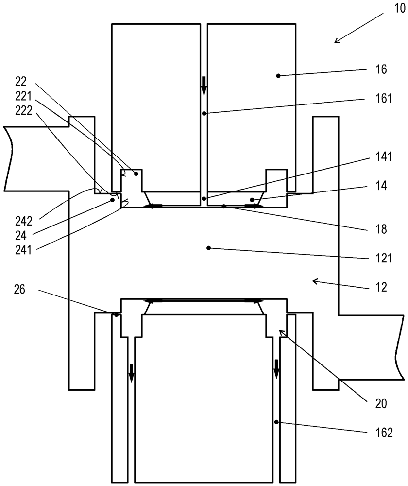
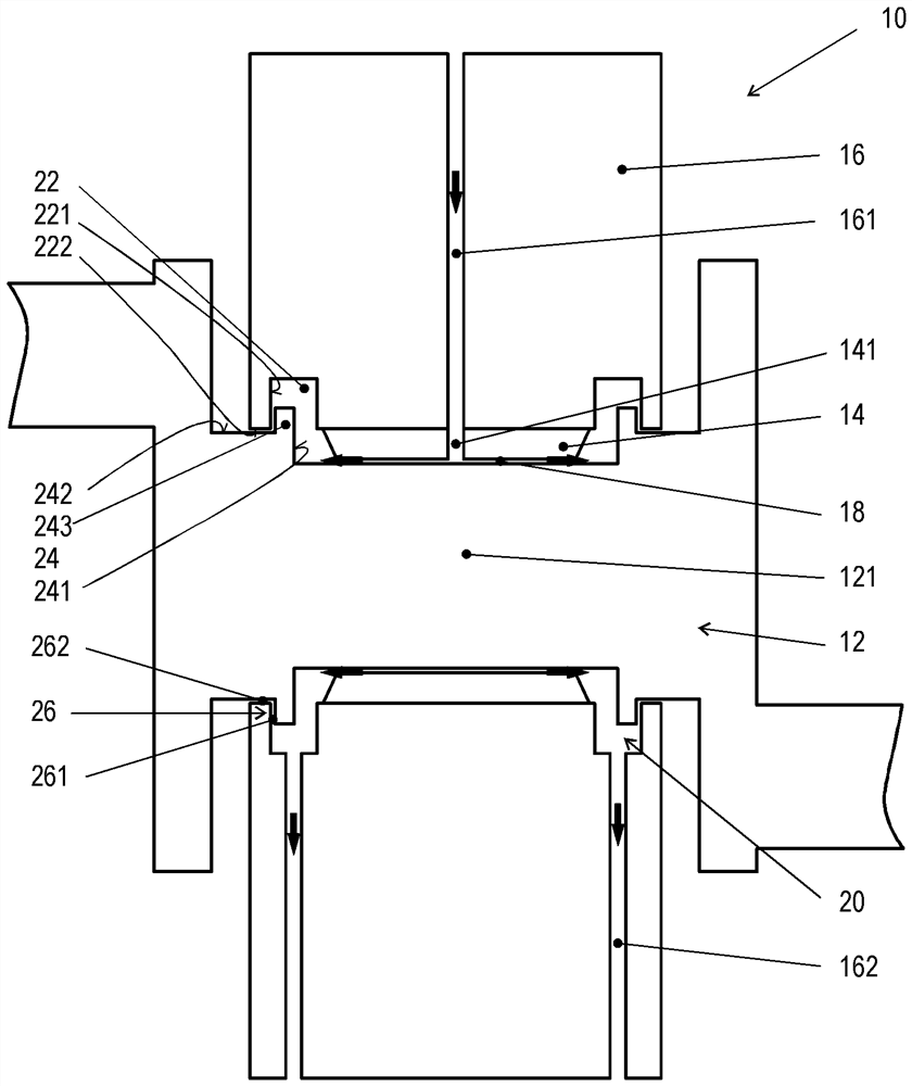
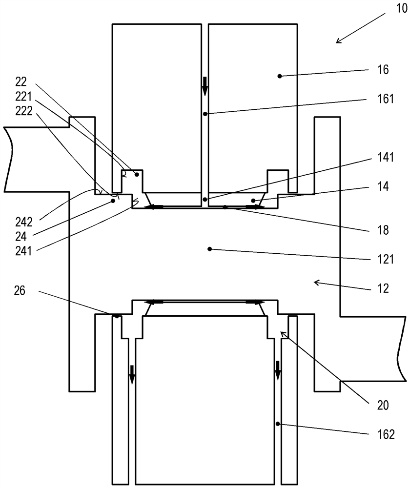
[0045] Figures 1 to 3A section through the crankshaft assembly 10 according to the invention is shown in each case and should, if possible, be discussed together first. In the following, reference is made to the individual drawings with regard to the specifics of the embodiments.

[0046] The crankshaft 12 is slidingly mounted in the region of its main journal 121 in a bearing receptacle 16 , which is fastened to the internal combustion engine housing, not shown in greater detail. This sliding bearing is realized by means of a bearing shell 14 , which is fixed on the bearing support 16 and forms a bearing gap 18 relative to the main journal 121 .

[0047] The bearing carrier 16 carries an oil feed channel 161 , which terminates in the through-bore 141 of the bearing shell 14 . Along this path, oil can be pressed from an oil reservoir (not shown) under pressure into the bearing gap 18 and in this way form the sliding film required for a low-friction bearing. In this case, a...


PUM


Abstract

The invention relates to a crankshaft assembly for an internal combustion engine, comprising a housing-fixed bearing support and a crankshaft with at least one main journal, the main journal being fixed at the bearing support by means of a bearing shell forming a bearing gap with the main journal Mounted rotatably on a bearing carrier, wherein the bearing carrier has an oil supply channel, which is in connection with a through-bore extending radially through the bearing shell, and wherein on both sides axially outside the bearing gap there is an oil-separating wall Axially outwardly delimited oil collector chamber, which is in connection with at least one oil drain channel in the bearing support. The invention is distinguished by the fact that the bearing carrier has a circumferential annular groove on both sides axially outside the bearing gap, and that the main journal has a circumferential annular seat on both sides axially outside the bearing gap, wherein the annular groove The axially outer groove wall and the seat wall of the associated annular seat each form separate sections of the respective oil barrier wall via a sealing gap.

Description

technical field [0001] The invention relates to a crankshaft assembly for an internal combustion engine, comprising a housing-fixed bearing carrier and a crankshaft with at least one main journal, the main journal being rotatable by means of a bearing shell fixed at the bearing carrier forming a bearing gap with the main journal is supported on the bearing support, wherein the bearing support has an oil supply channel, which is in connection with the through-bore radially penetrating through the bearing shell, and wherein, on both sides, on the axially outer side of the bearing gap, there is a through oil barrier Axially outwardly delimited oil collector chamber, which is in connection with at least one oil drain channel in the bearing support. Background technique [0002] Such a crankshaft assembly for an internal combustion engine is known from DE 10 2007 023 107 A1. [0003] The crankshaft of an advanced internal combustion engine is typically supported via slide bearin...

Claims


Application Information

Patent Timeline
Patent Type & Authority Patents(China)
IPC IPC(8): F16C9/02F16C3/14F16C33/10
CPCF16C9/02F16C3/14F16C33/1025F16C2360/22F16C33/1045F16C33/743
Inventor K.伯恩斯特德特
Owner VOLKSWAGEN AG
Learn More