Compressed air heat exchange system

A technology of heat exchange system and compressed air, which is applied in the direction of air conditioning system, compressor, space heating and ventilation, etc. It can solve the problems of environmental hazards and inability to realize the humidification function, and achieve the reduction of environmental hazards, simple structure, and less small footprint effect

Pending Publication Date: 2020-01-21
GD MIDEA AIR-CONDITIONING EQUIP CO LTD
View PDF7 Cites 12 Cited by
  • Summary
  • Abstract
  • Description
  • Claims
  • Application Information

AI Technical Summary

Problems solved by technology

[0002] In the related art, the heat exchange system with cooling and / or heating function can usually only perform dehumidification operation, but cannot realize the humidification function. In addition, the refrigerant used in the above heat exchange system is harmful to the environment, such as the greenhouse effect, the ozone layer hollow

Method used


Image

  • Compressed air heat exchange system
  • Compressed air heat exchange system
  • Compressed air heat exchange system

Examples


Embodiment 1

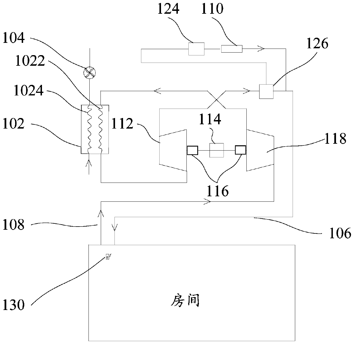
[0058] Such as figure 1 As shown, the compressed air heat exchange system includes: processor (see Figure 8 ), pressurized expansion assembly, heat exchanger 102, fan 104 and humidification module 110.

[0059] Among them, the processor is used to execute computer instructions.

[0060] The heat exchanger 102 includes an outer circulation flow path 1024 and an inner circulation flow path 1022 arranged in parallel, and both ends of the outer circulation flow path 1024 communicate with the outside.

[0061] The fan 104 is arranged on the outer circulation flow path 1024 and is electrically connected to the processor for driving outdoor air to flow through the outer circulation flow path 1024 .

[0062] The pressurized expansion assembly is electrically connected to the processor and can communicate with the internal circulation flow path 1022. An air outlet flow path 106 and a return air flow path 108 are also provided between the pressurized expansion assembly and the room t...

Embodiment 2

[0076] Such as figure 1 As shown, the compressed air heat exchange system according to this embodiment may only have cooling and humidifying functions based on different pipeline connection modes.

[0077] Specifically, the expander 112 is connected to the air outlet flow path 106 and is connected to the outlet end of the internal circulation flow path 1022, and the compressor 118 is connected to the return air flow path 108 and is connected to the inlet end of the internal circulation flow path 1022, wherein the indoor The air enters the compressor 118 through the return air flow path 108 to heat up, enters the inner circulation flow path 1022 and exchanges heat with the outer circulation flow path 1024 to cool down, returns to the expander 112 for further cooling, and then returns to the room through the air outlet flow path 106 .

Embodiment 3

[0079] Such as figure 1As shown, on the basis of the second embodiment, the humidification module 110 is further provided with a water tank 124; it also includes: a first gas-liquid separator 126, which is arranged on the air outlet flow path 106, and is arranged on the pressurized expansion assembly and Between the connection point between the humidifying module 110 and the air outlet flow path 106 , the first gas-liquid separator 126 can communicate with the water tank 124 , and is used to separate the condensed water precipitated in the air flow path 106 and introduce it into the water tank 124 when cooling the room.

[0080] In this embodiment, in the refrigeration mode, the air outlet flow path 106 is used to output low-temperature gas, and in the process of being transported to the room, it passes through the first gas-liquid separator 126, and the first gas-liquid separator 126 separates the condensed water , the gas is input into the chamber, and the liquid is introduc...


PUM


Abstract

The invention provides a compressed air heat exchange system. The compressed air heat exchange system comprises a heat exchanger, a draught fan, a boosting expansion assembly and a humidifying module,wherein the heat exchanger comprises an outer circulation flow passage and an inner circulation flow passage; the two ends of the outer circulation flow passage communicate with the outdoor; the draught fan is arranged on the outer circulation flow passage, electrically connected with a processor and used for driving outdoor air to flow through the outer circulation flow passage; the boosting expansion assembly is electrically connected with the processor and can communicate with the inner circulation flow passage; an air outlet flow passage and an air return flow passage are further arrangedbetween the boosting expansion assembly and the indoor, so that the boosting expansion assembly receives indoor air through the air return flow passage and conducts heating or cooling on the indoor through the air outlet flow passage; the humidifying module is electrically connected with the processor and can communicate with the air outlet flow passage; and the processor is further used for executing computer instructions so as to implement the following steps of controlling the humidifying module to operate to conduct humidification on the indoor through the air outlet flow passage. Throughimplementation of the technical scheme, the air is adopted as a coolant to replace a compound cooling agent adopted in the correlation technology, and harm to the environment is reduced through combined operation of a compressor and an expansion machine.

Description

technical field [0001] The present application relates to the field of household operation control, in particular, to a compressed air heat exchange system. Background technique [0002] In the related art, the heat exchange system with cooling and / or heating function can usually only perform dehumidification operation, but cannot realize the humidification function. In addition, the refrigerant used in the above heat exchange system is harmful to the environment, such as the greenhouse effect, the ozone layer hollow. Contents of the invention [0003] This application aims to solve at least one of the technical problems existing in the prior art or related art. [0004] For this reason, the purpose of this application is to propose a new compressed air heat exchange system. [0005] In order to achieve the above purpose, according to the technical solution of the present application, a compressed air heat exchange system is proposed, which specifically includes: a proce...

Claims


Application Information

Patent Timeline
Patent Type & Authority Applications(China)
IPC IPC(8): F25B41/04F25B9/00F24F11/64F24F1/0087F24F110/20F25B41/20
CPCF25B9/004F24F11/0008F24F11/64F24F1/0087F25B2600/25F24F2110/20F25B41/20
Inventor 赵帅白崇俨魏留柱朱兴丹袁紫琪
Owner GD MIDEA AIR-CONDITIONING EQUIP CO LTD
Why Eureka
Try Eureka