
Display device, electronic equipment and manufacturing method of display device

A display device and display panel technology, which is applied to branch equipment, telephone communication, electrical components, etc., can solve the problems of poor coating accuracy on the periphery of the light-transmitting area, and achieve the effect of reducing the number of dispensing times, avoiding light leakage, and effectively shading light.

Inactive Publication Date: 2020-01-21
WUHAN CHINA STAR OPTOELECTRONICS TECH CO LTD
View PDF9 Cites 15 Cited by
  • Summary
  • Abstract
  • Description
  • Claims
  • Application Information

AI Technical Summary

Problems solved by technology

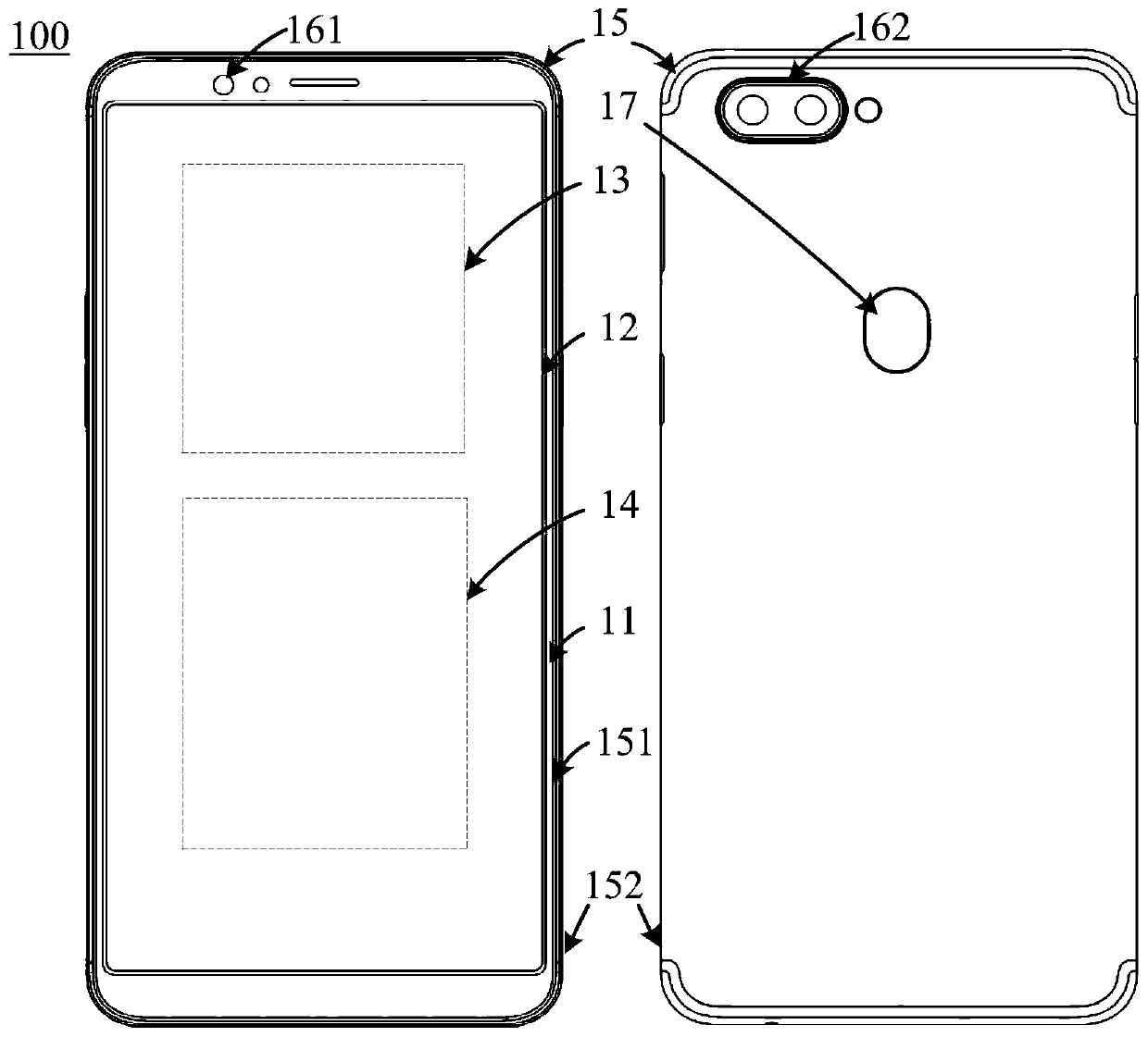
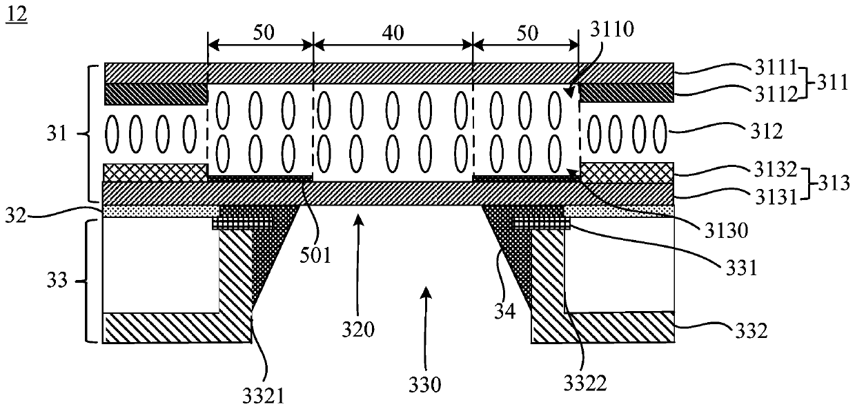
[0003] The embodiment of the present application provides a display device, electronic equipment and a manufacturing method of the display device to solve the technical problem of poor coating accuracy around the light-transmitting area when the display panel is assembled with the backlight module

Method used


Image

  • Display device, electronic equipment and manufacturing method of display device
  • Display device, electronic equipment and manufacturing method of display device
  • Display device, electronic equipment and manufacturing method of display device

Examples


Embodiment Construction

[0034] The following will clearly and completely describe the technical solutions in the embodiments of the present application with reference to the accompanying drawings in the embodiments of the present application. Obviously, the described embodiments are only part of the embodiments of the present application, not all of them. Based on the embodiments in this application, all other embodiments obtained by those skilled in the art without making creative efforts belong to the scope of protection of this application.

[0035] In the description of the present application, it is to be understood that the terms "centre", "thickness", "upper", "lower", "vertical", "horizontal", "inner", "outer", "side" etc. indicate The orientation or positional relationship is based on the orientation or positional relationship shown in the drawings, and is only for the convenience of describing the application and simplifying the description, rather than indicating or implying that the device...


PUM


Abstract

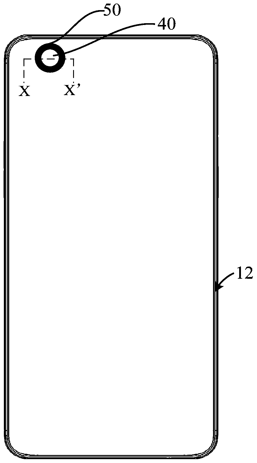
Embodiments of the invention disclose a display device, electronic equipment and a manufacturing method of the display device. The display device comprises a display panel, a polarizer, a backlight module and shading glue, wherein the display panel is provided with a light-transmitting area and a shading area, and the shading area is arranged around the periphery of the light-transmitting area; the polarizer is arranged on the display panel, a first through hole is formed in the polarizer, and the first through hole is arranged to correspond to the light-transmitting area; the backlight moduleis arranged on the polarizer, a second through hole is formed in the backlight module, and the second through hole is arranged to correspond to the light-transmitting area; and the shading glue is arranged on the periphery of the hole wall of the second through hole and extends to the periphery of the hole wall of the first through hole. According to the scheme, the glue dispensing frequency during assembly of the display device is reduced and the coating precision of the periphery of the light-transmitting area is improved.

Description

technical field [0001] The present application relates to the field of display technology, in particular to a display device, electronic equipment and a manufacturing method of the display device. Background technique [0002] With the continuous development and improvement of display devices, display devices with higher screen-to-body ratios and more stunning display effects have gradually become mainstream. The existing blind hole technology forms a light-transmitting area on the display panel through openings in the screen, and places devices such as the front camera under the display screen to achieve a full-screen display effect. However, when the display panel and the backlight module are assembled, It is necessary to apply the light-shielding glue twice on the area corresponding to the edge of the light-transmitting area. Due to the coating accuracy and the first dispensing operation, it is easy to cause glue overflow, resulting in poor coating accuracy around the lig...

Claims


Application Information

Patent Timeline
Patent Type & Authority Applications(China)
IPC IPC(8): G02F1/1335G02F1/13
CPCG02F1/133512G02F1/1303H04M1/0266H04M1/0264G02F1/133331G02F1/133388G02F1/133514G02F1/133528
Inventor 余朋飞龙冲宋涛唐维
Owner WUHAN CHINA STAR OPTOELECTRONICS TECH CO LTD
Learn More