Heat coating device and heat coating process method

A thermal coating and workpiece technology, applied to the device and coating of the surface coating liquid, can solve the problems of large randomness, harsh working environment, and much dust, and achieve easy recycling and good thermal coating quality , solve the effect of more dust

Active Publication Date: 2020-01-24
广东省机械研究所有限公司
View PDF7 Cites 9 Cited by
  • Summary
  • Abstract
  • Description
  • Claims
  • Application Information

AI Technical Summary

Problems solved by technology

However, in the thermal coating device of the prior art, it is difficult to ensure the fluidization effect of the thermal coating powder, and the immersion process of the workpiece in the thermal coating process is artificially operated, which is arbitrarily large, and the immersion process is relatively simple, so it is difficult to make the surface of the workpiece Full contact with the powder in the fluidized state makes it difficult to ensure the stability of the thermal coating quality, and lacks effective monitoring of the temperature of the thermally coated workpiece, which is prone to problems that affect the coating quality due to abnormal temperature of the workpiece, and thermal coating construction There is a lot of dust in the area, and the working environment is relatively harsh

Method used


Image

  • Heat coating device and heat coating process method
  • Heat coating device and heat coating process method
  • Heat coating device and heat coating process method

Examples


Embodiment Construction

[0026] In order to make the object, technical solution and advantages of the present invention clearer, the present invention will be further described in detail below in conjunction with the accompanying drawings and embodiments. It should be understood that the specific embodiments described here are only used to explain the present invention, not to limit the present invention.

[0027]When an element is referred to as being "connected to" another element, it can be directly connected to the other element or indirectly connected through intervening elements.

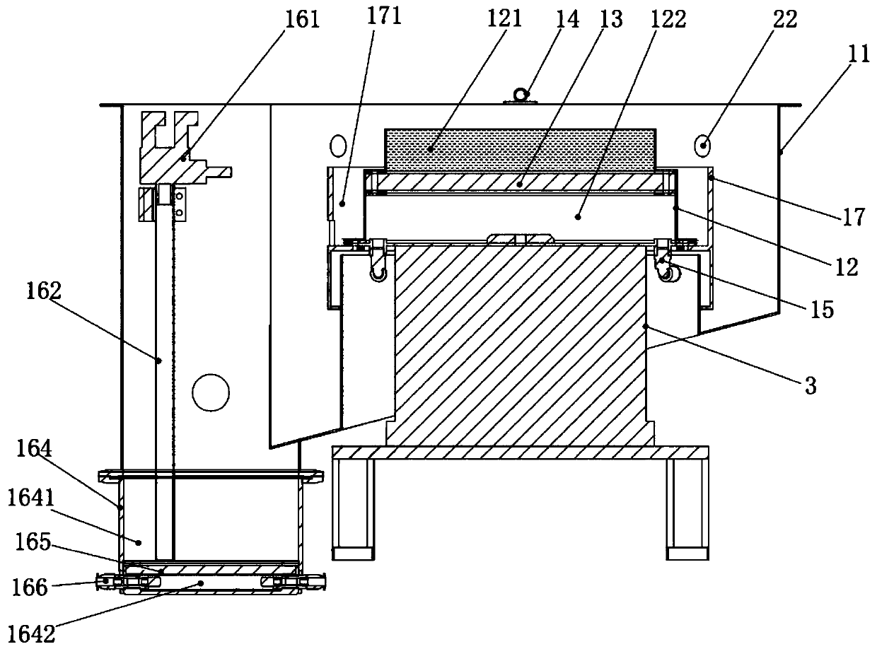
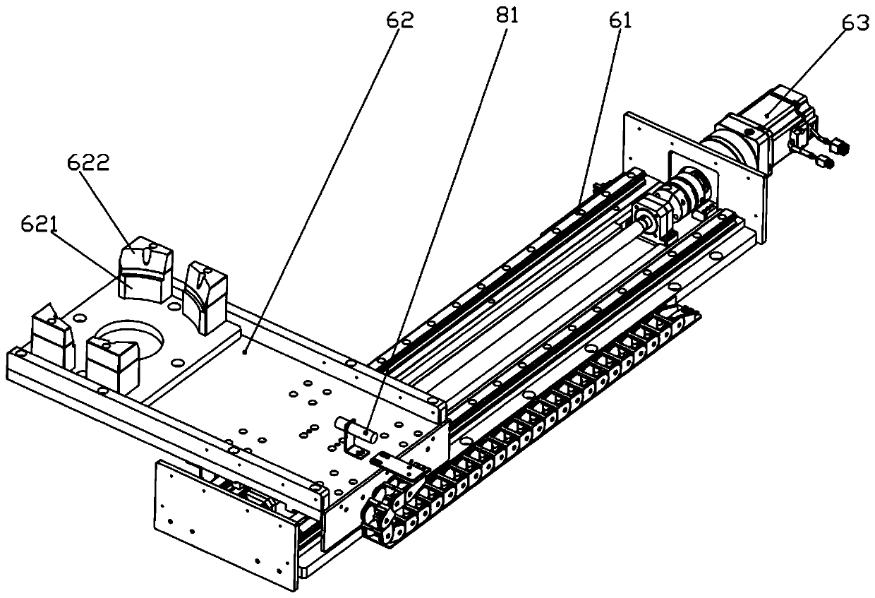
[0028] Such as Figure 1-5 As shown, a thermal coating device includes a fluidized bed 1, a powder recovery mechanism, a vibrator 3, a workpiece grasping mechanism 4, a rotating mechanism 5, a workpiece conveying mechanism 6, a cold dryer 7 and a control device 8, and the fluidized The bed 1 includes a dust collection hood 11, a fluidization chamber 12 arranged in the dust collection hood 11 with the opening facing u...


PUM


Abstract

The invention relates to the technical field of heat coating, in particular to a heat coating device and a heat coating process method. The heat coating device comprises a workpiece grabbing mechanism, a rotating mechanism and a fluidized bed. The fluidized bed comprises a dust collection hood, a fluidized bin arranged in the dust collection hood and a first fluidized plate arranged in the fluidized bin. The fluidized bin is divided by the first fluidized plate into a fluidized pool and a first air inflation cavity up and down. The first inflation cavity communicates with the fluidized pool through micropores in the first fluidized plate. Feeding openings are formed above the fluidized pool. The first air inflation cavity is provided with a first air inlet. The workpiece grabbing mechanismcan grab to-be-coated heated workpieces, and the to-be-coated portions of the workpieces are stretched in or moved out of the fluidized pool. The rotating mechanism can enable the workpieces and thefluidized pool to rotate oppositely. The heat coating device has the advantages that the fluidization effect of heat coating powder is good, the workpiece immersion procedure in the heat coating process is quite reasonable, the workpieces can be in sufficient contact with the heat coating powder in a fluidized state, and stability of heat coating quality can be improved.

Description

technical field [0001] The invention relates to the technical field of thermal coating, in particular to a thermal coating device and a thermal coating process method. Background technique [0002] Thermal coating of epoxy resin powder on workpieces (such as stator or rotor coils) is a common insulation treatment process. This process has the following requirements: (1) The workpiece needs to be heated to a specific temperature before coating. temperature, and the temperature of the workpiece has an impact on the coating effect; (2) hot coating powder (epoxy resin powder) needs to be fluidized first (that is, the hot coating powder is blown from the stacked state to the raised and rolled state by air flow, similar to (3) When the workpiece is thermally coated, it needs to be immersed in the thermal coating powder in a fluidized state and fully contact with the powder, so that the powder is adsorbed to the surface of the workpiece and solidified. It can be seen that the flui...

Claims


Application Information

Patent Timeline
Patent Type & Authority Applications(China)
IPC IPC(8): B05C19/02B05C13/02B05C19/06
CPCB05C19/02B05C13/02B05C19/06
Inventor 张福沐唐亮谭思达丘院震张沈佳曾建胜
Owner 广东省机械研究所有限公司
Why Eureka
Try Eureka