
Eureka
For R&D, Eureka makes reading and utilizing patents & technical documents easy.
Eureka AIR
Designed for self-driven R&D workflows. Generate viable solutions, solve complex R&D challenges, empower your innovation with AI.

Eureka Materials
Designed for material experts only. Revolutionize your material R&D, from search, analyze, to developing new materials.

TechResearch
Generate reliable direction feasibility study reports for your R&D in just a few steps.

TechSeek
Discover and master advanced knowledge NOW. Basics, ideas, possibilities, all at once.

TechMind
As an expert in R&D Theories, TechMind can generates customized viable solutions instantly.

TechRisk
Analyze your overall solution with one click, know your potential R&D risks in advance.

TechMonitor
Get weekly tech updates, stay abreast of the latest tech innovations and key insights.
Fixing device for bridge pier drainage and operating method thereof
A technology for fixing devices and bridge piers, which is applied in the direction of bridges, bridge parts, bridge construction, etc. It can solve the problems of unstable fixing of pier drain pipes and blockage of drain pipes, and achieve the effects of improving construction efficiency, efficient fixing, and ensuring stability
- Summary
- Abstract
- Description
- Claims
- Application Information
AI Technical Summary
Problems solved by technology
Method used
Image

Examples
Embodiment 1
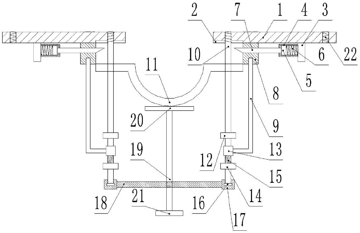
[0023] like figure 1 As shown, a fixing device for pier drainage includes a fixing unit and a connecting plate 18, the fixing unit is symmetrically fixed at both ends of the connecting plate 18, and the fixing unit includes a base 1, a positioning rod 10 and a L type rod 9,
[0024] The lower surface of the base 1 is sequentially provided with a first fixing block 8 and a clamping part from the inside to the outside, and the clamping part includes a support plate 3, a first sleeve 4 and a square rod 7, and the first sleeve 4 A positioning block 5 is arranged inside, and a first spring 6 is fixed between the positioning block 5 and the support plate 3 , and one end of the square rod 7 passes through the first sleeve 4 and is fixedly connected with the positioning block 5 , the other end runs through the first fixed block 8 and the end is set as an inclined section;
[0025] The upper end of the positioning rod 10 is threadedly connected with the base 1, and the middle and low...
Embodiment 2
[0036] like figure 1 As shown, a method for operating a fixing device for pier drainage includes the following specific steps:
[0037] Step 1: Adjust the distance between the two bases 1 according to the diameter of the drain pipe, and then fix the two bases 1 on the wall;
[0038] Step 2: Then put the drain pipe between the two bases 1;
[0039] Step 3: Pull down the L-shaped rod 9, and the second sleeve 13 fixedly connected with it acts on the second spring 15, so that the positioning rod 10 is aligned with the matching hole on the base 1, and then manually rotate the positioning rod 10, The positioning rod 10 is threadedly connected to the base 1;
[0040] Step 4: The upper end of the L-shaped rod 9 is aligned with the hole at the lower end of the first fixed block 8, the L-shaped rod 9 is released, the second spring 15 resets, and its force acts on the second sleeve 13 to insert the top end of the L-shaped rod 9 in the hole;
[0041] Step 5: Turn the handle 21, and th...
PUM
 Abstract
Description
Claims
Application Information
 - R&D Engineer
- R&D Manager
- IP Professional
- Industry Leading Data Capabilities
- Powerful AI technology
- Patent DNA Extraction
Browse by: Latest US Patents, China's latest patents, Technical Efficacy Thesaurus, Application Domain, Technology Topic, Popular Technical Reports.
© 2024 PatSnap. All rights reserved.Legal|Privacy policy|Modern Slavery Act Transparency Statement|Sitemap|About US| Contact US: help@patsnap.com