Maximum wave energy tracking system based on wave energy buoy light

A tracking system and buoy light technology, applied in the field of maximum wave energy tracking system, can solve problems such as large influence, and achieve the effect of improving efficiency and good stability

Inactive Publication Date: 2020-01-31
DALIAN MARITIME UNIVERSITY
View PDF6 Cites 4 Cited by
  • Summary
  • Abstract
  • Description
  • Claims
  • Application Information

AI Technical Summary

Problems solved by technology

Based on the buoy light of the maximum wave energy tracking system, the present invention proposes the principle of resonance to ensure that the speed of the motor mover is equal to the speed in the vertical direction of the wave, so as to solve the problem that the buoy light is greatly affected by waves when it is working, and improve the stability of work

Method used


Image

  • Maximum wave energy tracking system based on wave energy buoy light
  • Maximum wave energy tracking system based on wave energy buoy light
  • Maximum wave energy tracking system based on wave energy buoy light

Examples


Embodiment approach

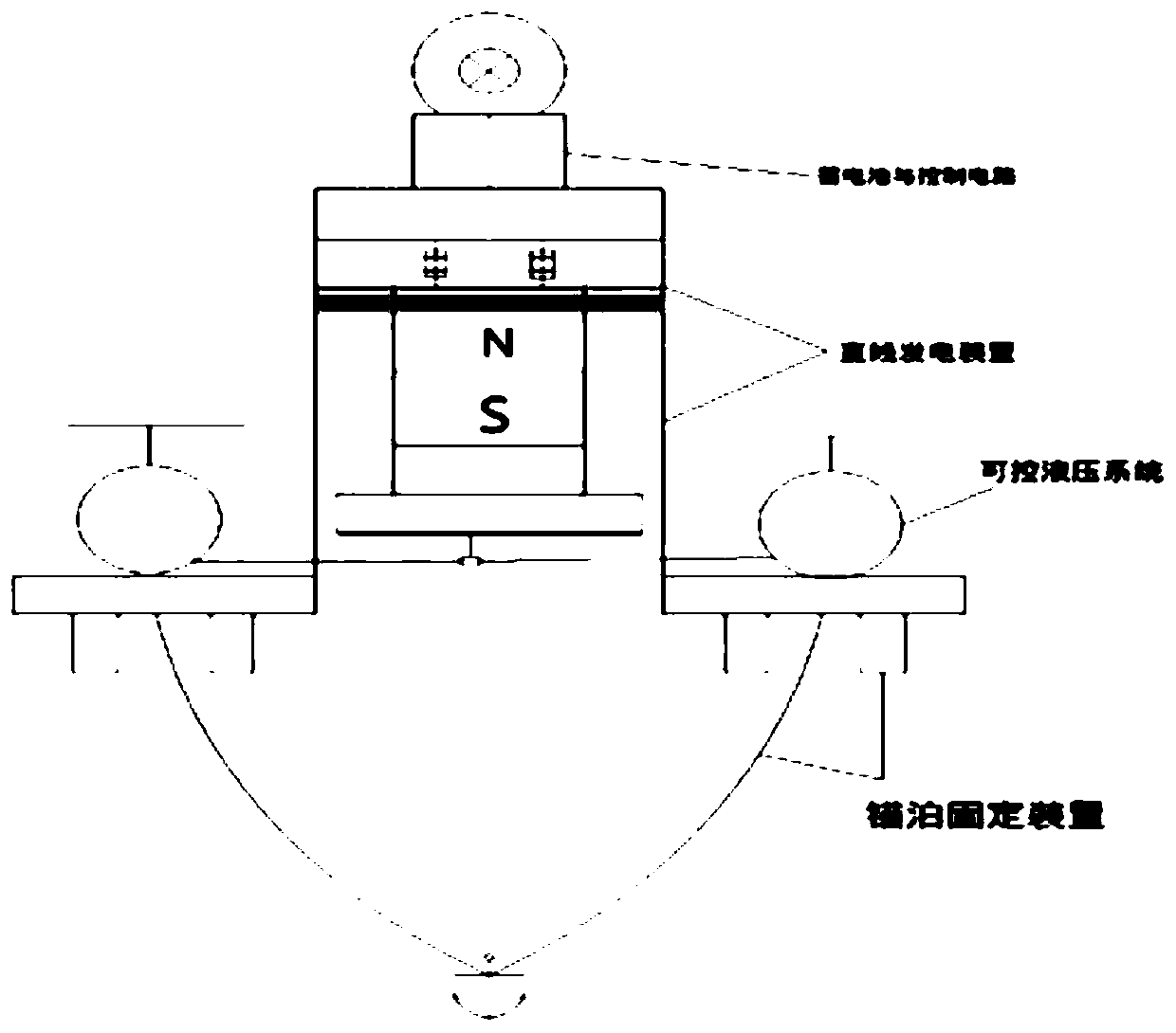
[0038] The wave energy harvesting device adopts a cylindrical oscillating buoy, which is used for ups and downs and swaying motions under the action of waves, and converts wave energy into electrical energy.

[0039]Further, as a preferred embodiment of the present invention

[0040] The linear generator device includes a permanent magnet, a floating plate, a buoy with a coil wound on its inner surface, and a battery installed above the buoy. The permanent magnet is fixed on the floating plate and arranged in the buoy with a coil wound on its inner surface. The buoy passes two A spring connects the permanent magnet. When it is on the river or sea surface, the ubiquitous waves can push the outer buoy to move up and down, while the permanent magnet floats up and down very little, the position of the coil equivalent to the magnet changes, and the coil cuts the magnetic induction line to generate an induced electromotive force.

[0041] Further, as a preferred embodiment of the p...


PUM


Abstract

The invention provides a maximum wave energy tracking system based on a wave energy buoy light, and relates to the field of buoy lights. In order to solve the problem of low efficiency of wave energyextraction in adopting wave energy to power the buoy light, the system comprises a wave energy acquisition device, a linear generator device, a buoy light circuit control system, a controllable hydraulic system and an anchoring fixture. The wave energy acquisition device is connected to the buoy light circuit control system, the linear generator device, the controllable hydraulic system and the anchoring fixture in sequence, and is connected to the seabed. The maximum wave energy tracking system based on the wave energy buoy light converts wave and tidal energy into electric energy through a wave energy generating device, thereby powering the floating buoy light for lighting and making full use of renewable resources of wave energy. Compared with solar energy and other new energies, the wave energy has the advantage of being less affected by the weather environment and having good stability. Meanwhile, the maximum wave energy tracking system based on the wave energy buoy light improvesthe efficiency of wave energy collection, and enables the buoy light to work continuously and efficiently.

Description

technical field [0001] The present invention relates to the technical field of buoy lights, in particular to a maximum wave energy tracking system based on wave energy buoy lights. Background technique [0002] At present, most of the navigation lights are powered by dry batteries, lead-acid batteries or air batteries. However, there are disadvantages such as relatively poor battery voltage stability, low energy utilization efficiency, short service life, difficult replacement, and high cost. Although it has been proposed to use new energy sources such as solar energy and wind energy, it is greatly affected by the environment and cannot work efficiently for a long time. Aiming at the problems that solar energy and other new energy buoy lights are greatly affected by the environment and work unstable, there have been cases where wave energy is used to power buoy lights, but the problem of low wave energy extraction efficiency has not yet been solved. Contents of the invent...

Claims


Application Information

Patent Timeline
Patent Type & Authority Applications(China)
IPC IPC(8): F03B13/20H02K35/04H02J7/00H02J7/32F21S9/03F21S9/04F21V23/00F21V23/04F21W111/043F21Y115/10
CPCF03B13/20F21S9/037F21S9/046F21V23/003F21V23/0464F21W2111/043F21Y2115/10H02J7/0031H02K35/04Y02E10/30
Inventor 王宁贾玉森付水孙岩涛白超王泊桦
Owner DALIAN MARITIME UNIVERSITY
Why Eureka
Try Eureka