Small current ground fault location method and system, monitoring device, equipment, medium

A small current grounding and fault location technology, applied in the field of distribution network, can solve problems such as high requirements for wave recording data, weak fault signals, and difficult detection, so as to improve application reliability, improve accuracy, and expand the opposite difference of mutation direction The effect of the coefficient

Active Publication Date: 2022-07-12
SHENZHEN POWER SUPPLY BUREAU
View PDF9 Cites 0 Cited by
  • Summary
  • Abstract
  • Description
  • Claims
  • Application Information

AI Technical Summary

Problems solved by technology

[0002] The neutral point of the 10kV and below medium and low voltage distribution network in my country is widely operated without grounding or grounding through the arc suppression coil. On the one hand, when a single-phase (small current) grounding fault occurs, the fault signal is weak and difficult to detect, while single-phase grounding Due to the high frequency of faults, numerous distribution network branches, and random load distribution, the location of small current ground faults has become a major technical problem in distribution network fault handling; , the remote transmission and storage of a large amount of wave recording data have high requirements on the master station and distributed terminals

Method used


Image

  • Small current ground fault location method and system, monitoring device, equipment, medium
  • Small current ground fault location method and system, monitoring device, equipment, medium
  • Small current ground fault location method and system, monitoring device, equipment, medium

Examples


Embodiment 1

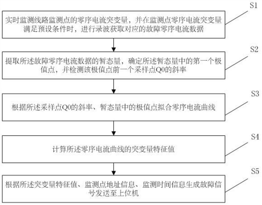
[0050] Embodiment 1 of the present invention provides a method for locating a small current ground fault, figure 1 For the flowchart of the method described in Embodiment 1, refer to figure 1 , the method described in the first embodiment includes the following steps:

[0051] Step S1, monitoring the zero-sequence current mutation of the line monitoring point in real time, and when the zero-sequence current mutation of the monitoring point meets a preset condition, perform wave recording to obtain corresponding fault zero-sequence current data;

[0052] Among them, the preset conditions are:

[0053] The zero-sequence current of the monitoring point line is sampled according to the preset sampling frequency. If the amplitude of n-1 or more sampling points in the n continuous sampling points satisfies the following formula (2), the recording is started to obtain the corresponding The fault zero-sequence current data is obtained and enter step S2, otherwise the wave recording ...

Embodiment 2

[0075] The second embodiment of the present invention provides a low-current grounding fault monitoring device, which is used to implement the steps of the low-current grounding fault monitoring method described in the first embodiment of the present invention, Figure 4 For a schematic diagram of the frame of the device described in the second embodiment, refer to Figure 4 , the device includes:

[0076] The monitoring and recording unit 1 is used for real-time monitoring of the zero-sequence current mutation of the line monitoring node, and when the zero-sequence current mutation of the monitoring point meets the preset condition, the recording is performed to obtain the corresponding fault zero-sequence current data;

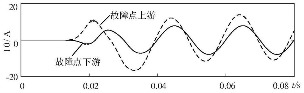
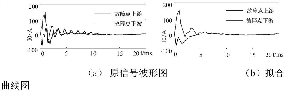
[0077] The node monitoring unit 2 is used to extract the transient value of the fault zero-sequence current data, determine the first extreme point in the transient value, and detect the sampling point Q before the extreme point 0 The slope of;

[0078] Th...

Embodiment 3

[0087] The third embodiment of the present invention proposes a low-current grounding fault location system, Figure 5 For the frame diagram of the system described in Embodiment 3, refer to Figure 5 , the system includes: a plurality of the small-current grounding fault monitoring devices 100, and a host computer 6; the plurality of monitoring devices are respectively arranged at a plurality of monitoring nodes of the line; the host computer 6 is used to detect the fault according to the fault The signal identifies the fault location. Specifically, the upper computer 6 is a master station or a distributed proxy terminal, and one upper computer 6 correspondingly receives fault signals of multiple monitoring devices 100 .

[0088] in, Image 6 This is a working flow chart of the low-current grounding fault location system described in this embodiment.

[0089] Wherein, the upper computer is specifically used for: when a positive angle fault occurs, if the S i (n)>0, it is ...


PUM


Abstract

The invention relates to a small-current grounding fault location method, system, monitoring device, equipment and medium. The monitoring points along the line detect the sudden change of zero-sequence current energy to quickly start, record the fault waveform, and then according to the upstream and downstream transient zero-sequence current sudden change of the fault point Reverse direction feature, calculate the positive and negative slope of the previous sampling point of the first extreme point of the zero-sequence current in the low frequency band including the power frequency, and use the cubic spline interpolation to fit the maximum point or minimum point in the original signal. Value point curve, finally calculate the eigenvalue of the mutation amount, and locate the fault according to the eigenvalue of the mutation amount. The storage medium is a computer-readable storage medium on which a computer program for implementing the reset control method is stored. The apparatus includes a processor and a memory in which the computer program is stored, and is capable of implementing the reset control method. By implementing the present invention, rapid fault location can be performed when a single-phase grounding fault occurs in a low-current grounding system.

Description

technical field [0001] The present invention relates to the technical field of power distribution networks, in particular to a small current grounding fault location method and system, a monitoring device, computer equipment, and a computer-readable storage medium. Background technique [0002] The neutral point of the medium and low voltage distribution network of 10kV and below in my country is widely used to operate without grounding or grounding through the arc suppression coil. On the one hand, when a single-phase (small current) grounding fault occurs, the fault signal is weak and difficult to detect. The high frequency of faults, the numerous branches of the distribution network and the random load distribution make the location of low-current grounding faults a major technical problem in distribution network fault handling; on the other hand, whether centralized or distributed location mode is used , the remote transmission and storage of a large number of recorded wav...

Claims


Application Information

Patent Timeline
Patent Type & Authority Patents(China)
IPC IPC(8): G01R31/08G01R31/52
CPCG01R31/086G01R31/088Y04S10/52
Inventor 黄福全李国栋董春林刘子俊王廷凰
Owner SHENZHEN POWER SUPPLY BUREAU
Why Eureka
Try Eureka