Optical fiber cutter and upper cover thereof

A cutting knife and optical fiber technology, which is applied in the coupling of optical waveguides, etc., can solve the problems of irregular cutting of optical fibers and unreliable pressing of optical fibers.

Pending Publication Date: 2020-01-31
SHENZHEN O FANS COMM TECH
View PDF0 Cites 0 Cited by
  • Summary
  • Abstract
  • Description
  • Claims
  • Application Information

AI Technical Summary

Problems solved by technology

[0003] The embodiment of the present application provides an optical fiber cleaver and its upper cover, which solves the problem that the fixed pressing block cannot firmly press the optical fiber in the case of dust and wear, resulting in irregular cutting of the optical fiber

Method used


Image

  • Optical fiber cutter and upper cover thereof
  • Optical fiber cutter and upper cover thereof
  • Optical fiber cutter and upper cover thereof

Examples


Embodiment Construction

[0026] In order to enable those skilled in the art to better understand the solutions of the application, the technical solutions in the embodiments of the application will be clearly and completely described below in conjunction with the drawings in the embodiments of the application. Obviously, the described embodiments are only It is a part of the embodiments of this application, but not all the embodiments. Based on the embodiments in this application, all other embodiments obtained by those of ordinary skill in the art without creative work fall within the protection scope of this application.

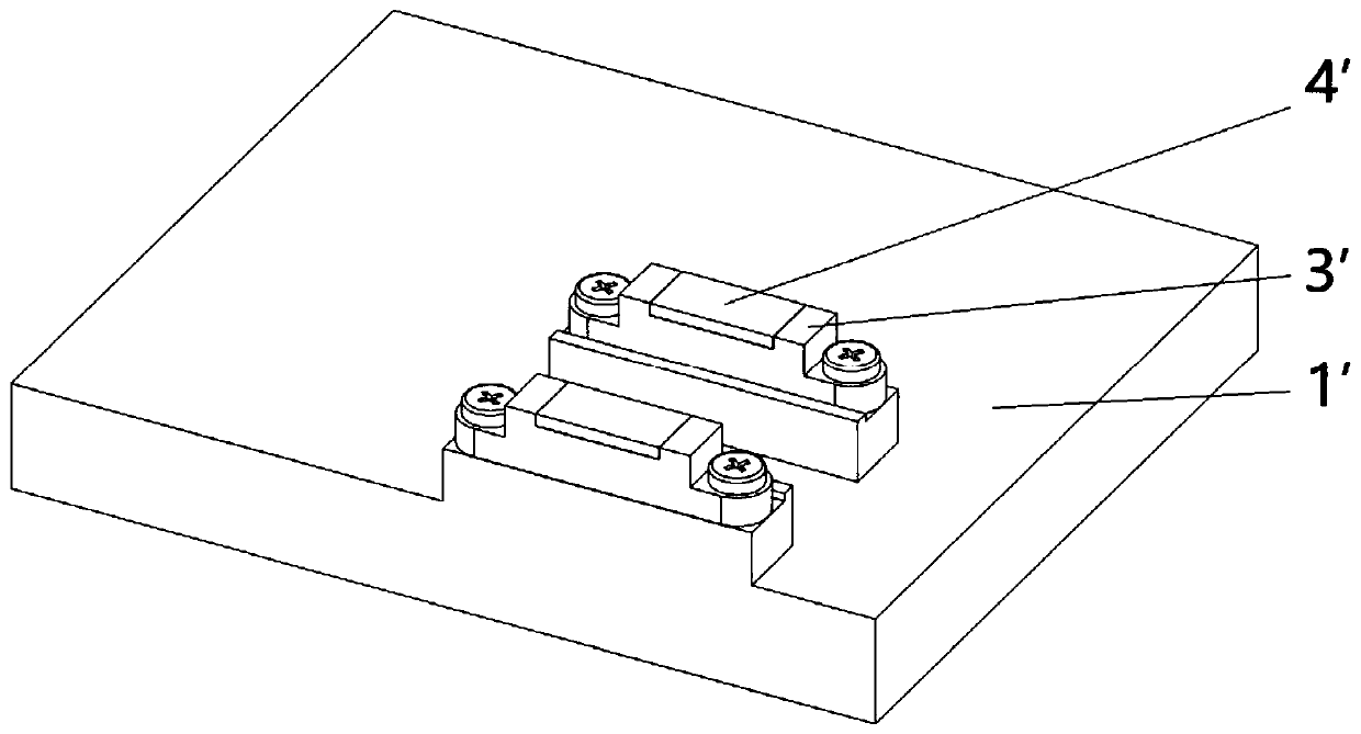
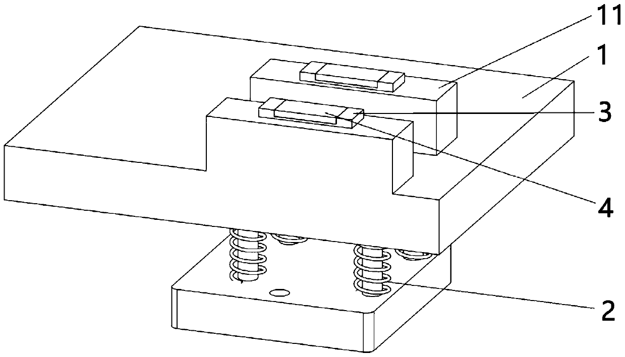
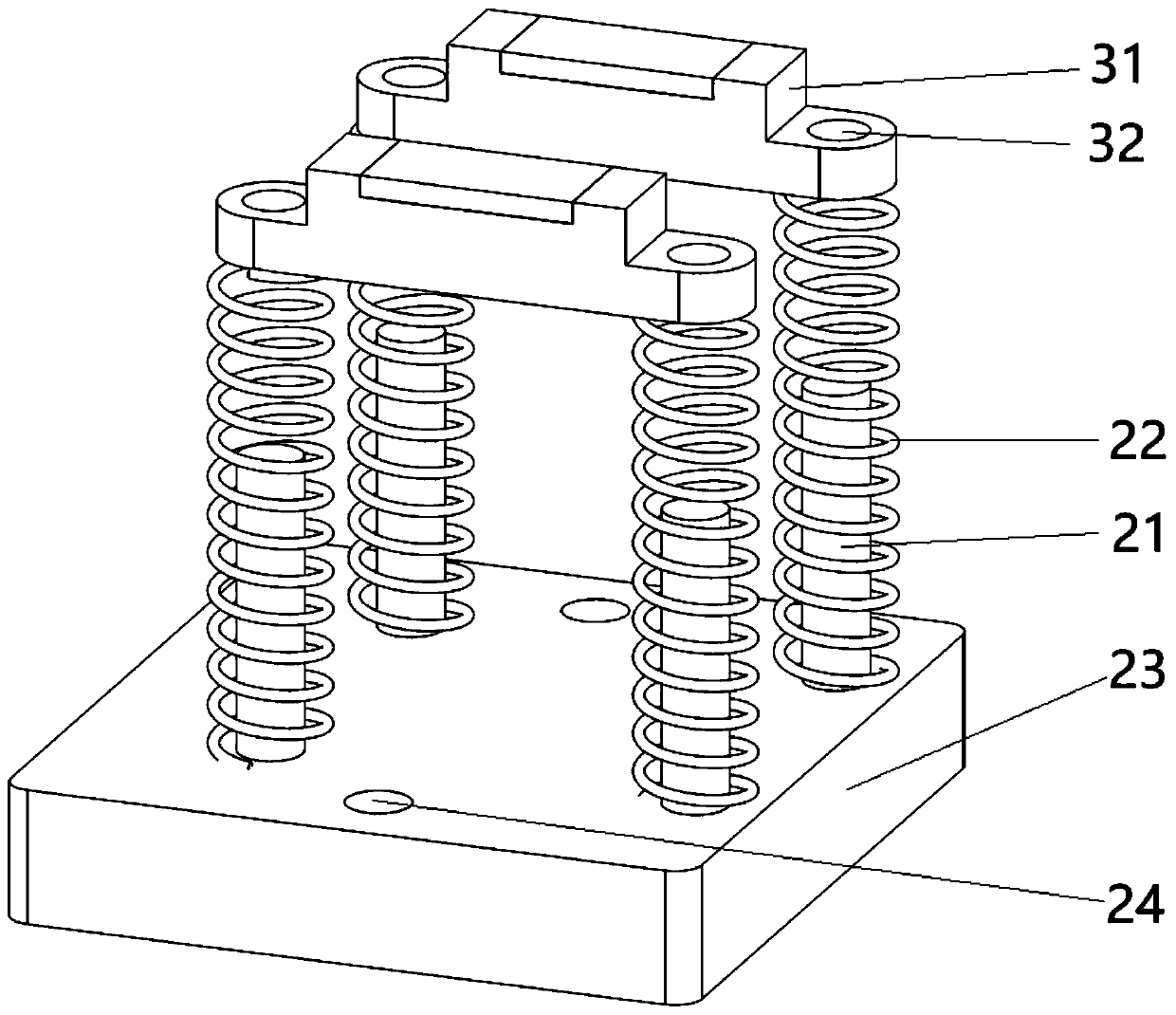
[0027] This application designs an optical fiber cleaver and its upper cover. Considering that the pressure block is fixed on the upper cover, when dust and foreign objects fall on the pressure pad or the two pressure pads are unevenly worn, it may cause two pressure pads. There is a height difference between the blocks, so that the optical fiber cannot be compressed, resulting in an...


PUM


Abstract

The embodiment of the invention discloses an optical fiber cutter and an upper cover thereof. The upper cover comprises a gland, a floating assembly, two pressing blocks arranged in parallel and pressing pads installed in pressing pad mounting parts of the pressing blocks respectively; through holes through which the pressure pad mounting parts pass are formed in the gland; the floating assembly comprises four connecting piece and spring groups; each connecting piece comprises a head part and a rod part; each rod part sequentially penetrates mounting holes of the spring and the pressing blockand is fixedly connected with the gland; and each spring is in a compressed state between the head part and the pressing block. The pressing blocks of the upper cover are set in floating type, and when the pressing blocks are cooperated with lower pressing blocks and clamp an optical fiber, the elastic force provided by the spring enables that the pressing blocks make tight contact with the optical fiber and clamps the optical fiber even if there is dust or wearing between the pressing blocks, and the problem that the optical fiber is cut irregularly due to the fact that a fixed pressing blockcannot firmly press the optical fiber under the dust and abrasion conditions is solved.

Description

Technical field [0001] This application relates to the technical field of cleavers, in particular to an optical fiber cleaver and its upper cover. Background technique [0002] During the use of the optical fiber cleaver, the two pressing pads of the upper cover and the main body of the cleaver need to properly press the optical fiber to fix the optical fiber on the cleaver. See figure 1 In the prior art, the pressure pad 4'is fixedly arranged on the pressure pad mounting part of the pressure block 3', and both ends of the pressure block 3'are fixed on the pressure cover 1'through the mounting holes. When foreign matter and dust fall on the pressure pad When the pressure pad 4'is worn on the 4'or used for a long time, the pressure of the 4 pressure pads on the optical fiber will be uneven, and the optical fiber cannot be firmly pressed, resulting in uneven cutting of the optical fiber. Summary of the invention [0003] The embodiment of the present application provides an optical...

Claims


Application Information

Patent Timeline
IPC IPC(8): G02B6/25
CPCG02B6/25
Inventor 何丕
Owner SHENZHEN O FANS COMM TECH
Why Eureka
Try Eureka